
Before I delve into some of the enhancements to Assemblies with SOLIDWORKS 2018, we should take a quick look at one of the proposed new features which didn’t made the initial SP0 release.
One of the areas. of the software, that has been stated for multiyear development by Dassault Systèmes SOLIDWORKS is that of Large Assemblies and Graphic Performance.
We saw with the preview of SOLIDWORKS 2018 at SOLIDWORKS World 2017 and then throughout SOLIDWORKS 2018 Beta that DS SOLIDWORKS has been working to enhance the capabilities of Large Design Review. First introduced in SOLIDWORKS 2012 Large Design Review allows for assemblies to open quickly as components are loaded only as graphics. These could be reset to Lightweight or Resolved to be worked on, but it was a one-way street. Once set to Lightweight or Resolved there was no going back!
DS SOLIDWORKS has been working on the capability within Large Design Review to allow components or sub-assemblies to be set to Lightweight or Resolved then after working on those components they could then be reverted to Graphic only. This could be done individually per component or all components could be reverted to Graphic from the top-level assembly. 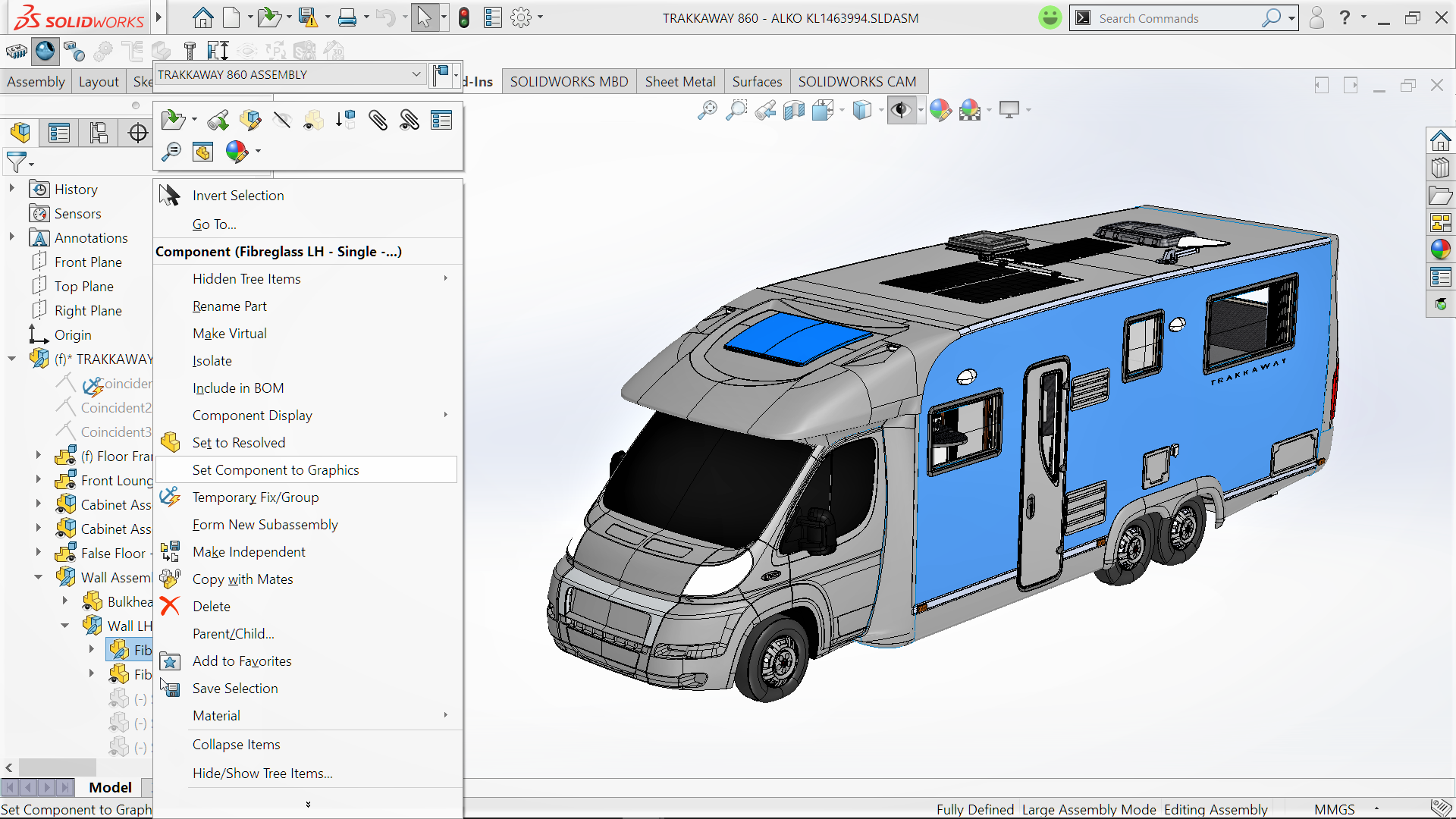 The other part of the development within Large Design Review was to be the ability to Creates Mates between Graphics Only components and components that were either lightweight or resolved!
With these couple of developments it could take Large Design Review from no longer just being a review tool but as the default once Large Assemblies have been created.
However Beta testing and the use of real life data has shown that these enhancement were not quite production ready. Taking the correct position DS SOLIDWORKS has held off the release of these features at this stage. I would think that with another six to eight months work on these development we will see them make a reappearance in SOLIDWORKS 2019 Beta.
A good example of a feature that required some more work before it made a release is Misaligned Concentric Mates. Initially shown in SOLIDWORKS 2017 Beta Misaligned Concentric Mates allows the mating of a pair of holes from two separate components to be mated concentrically, even if they are not of the same distant. It didn’t make the last release, partly due to some negative feedback but it’s functionality also looked to be not fully worked through! Last year I was not fully sold on the idea but a year on I think I have a better understand of why this has been developed. In part, I’m sure it is due to imported data from suppliers, being used within user produced products. Especially with the mixture of metric & imperial designed components.
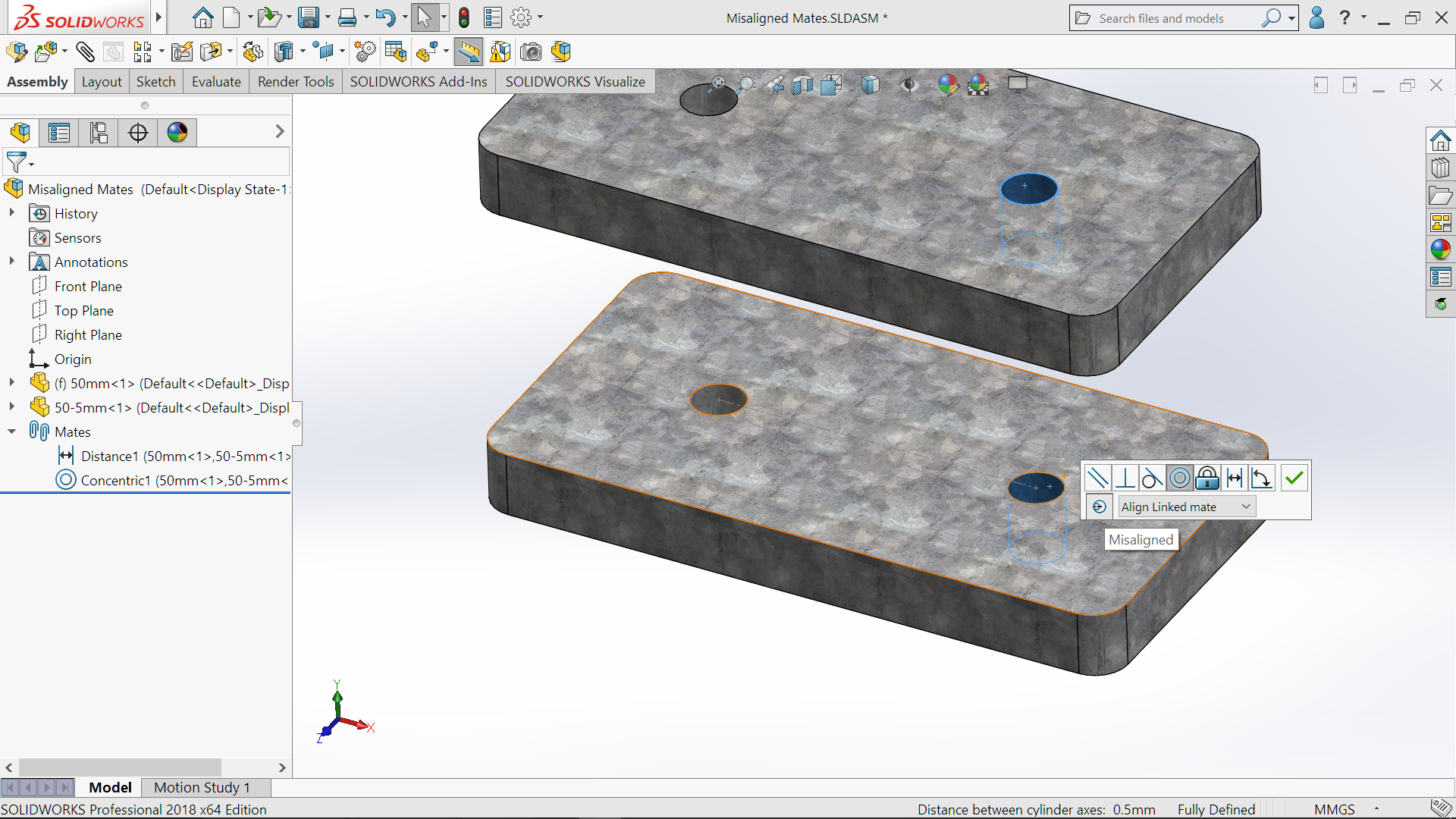
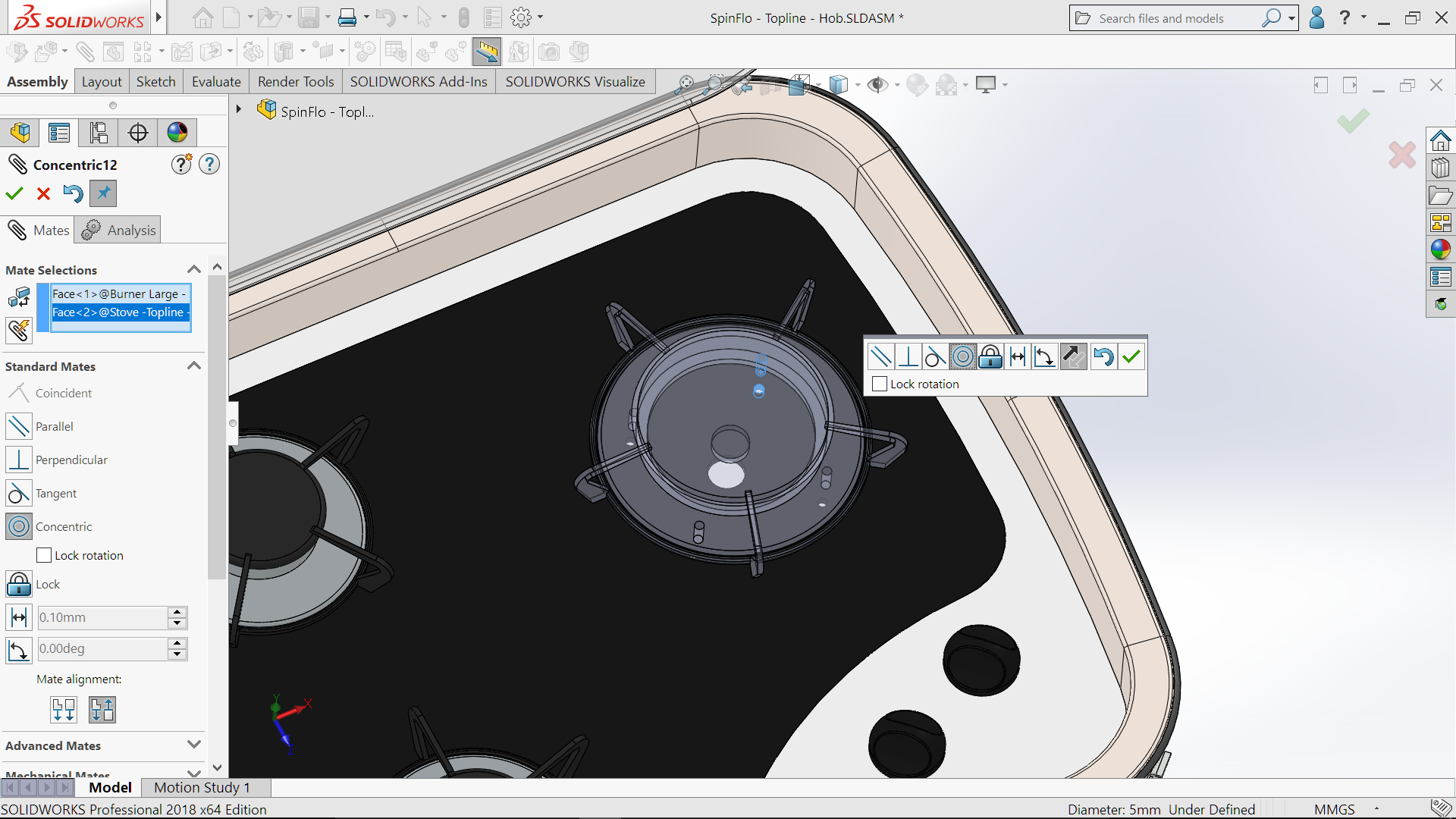
 More importantly it is not just the same feature reintroduced. The process of adding the misalignment is far more in line with other standard mates. Add the first concentric mate, then when adding the second concentric mate it brings up a small dialogue box which allows the alignment selection
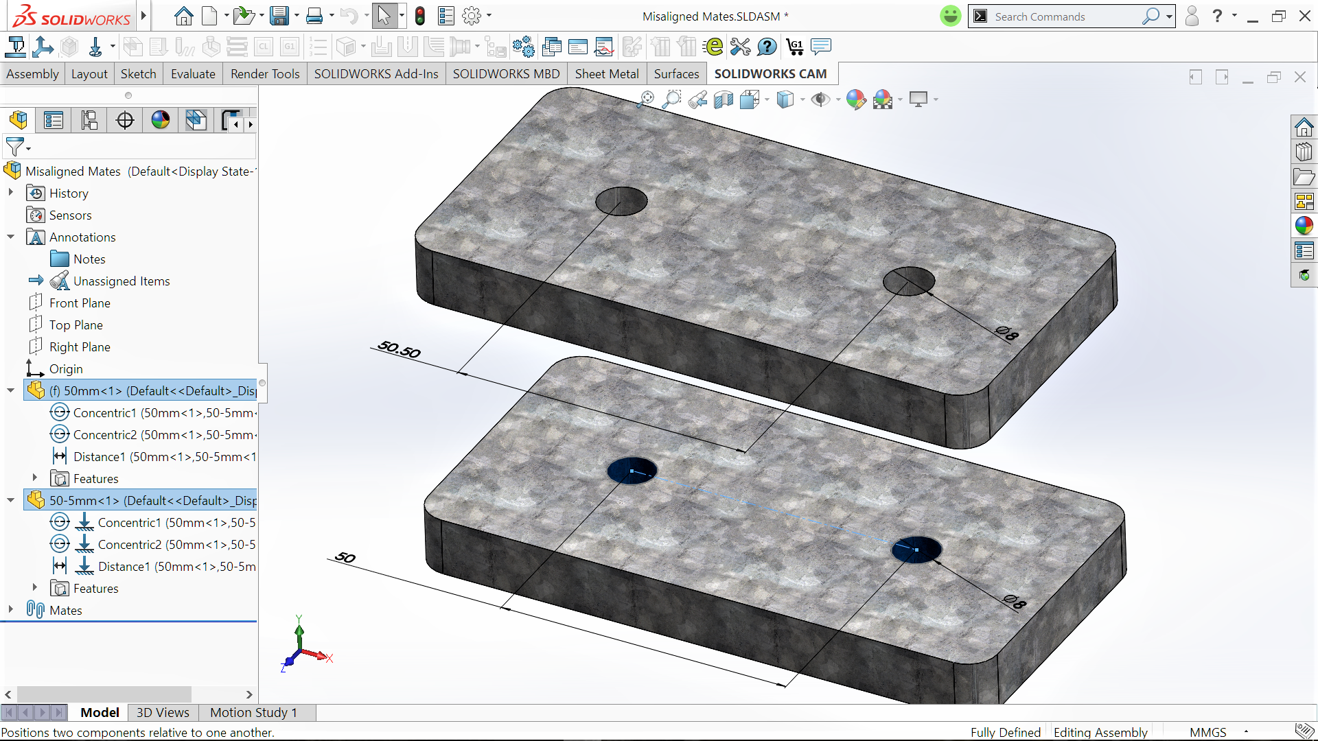
 Under Mates the icon depicts which mate is offset or shows if the mates are symmetrical.
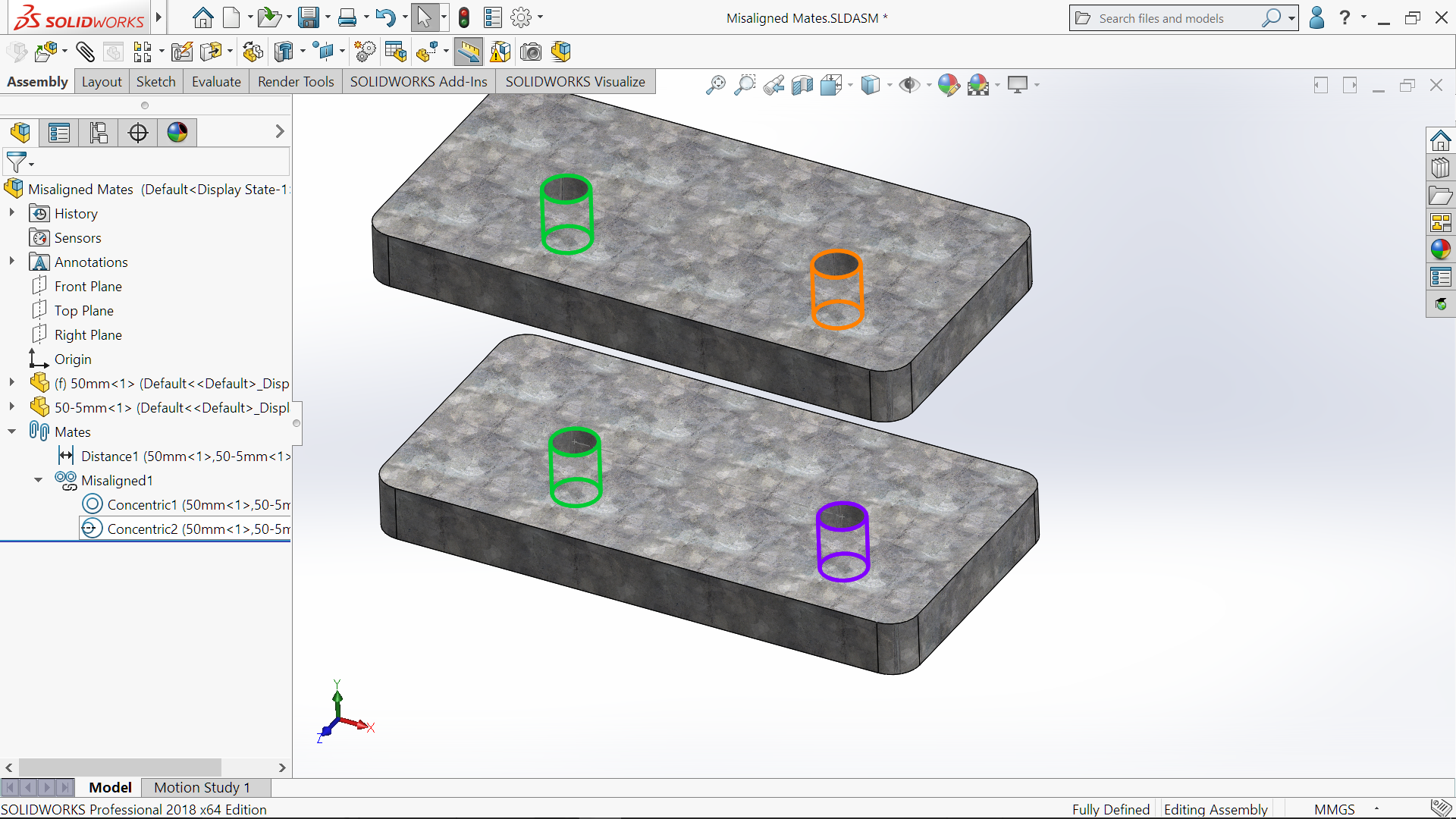 Editing the Misaligned Mate also allows the option of how to treat the misalignment. It shows graphically which is misaligned and further setting allow changes to the maximum deviation, within the Mates PropertyManager.
 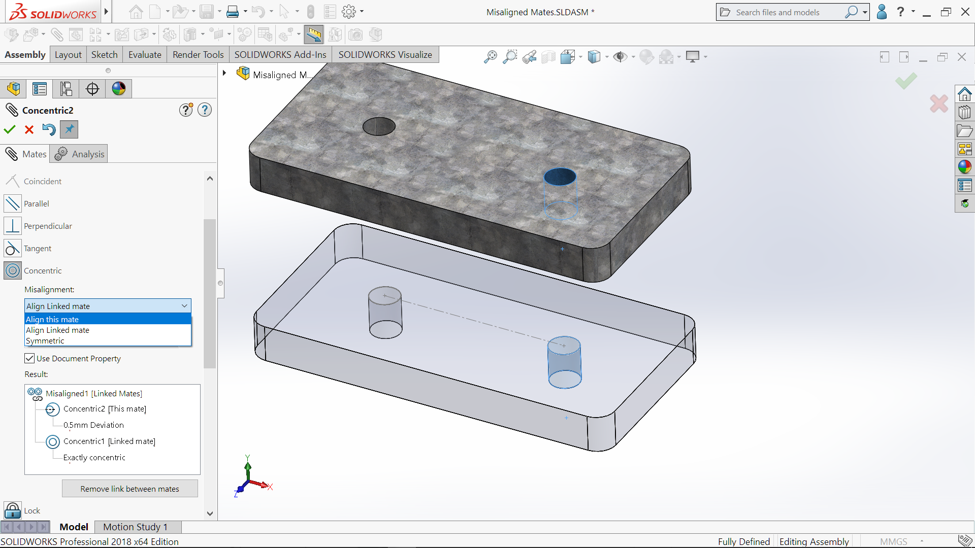 For those so aggrieved with the thought of having concentric mates, not so concentric, the option can be set to either allow or not allow from the System Options> Assemblies
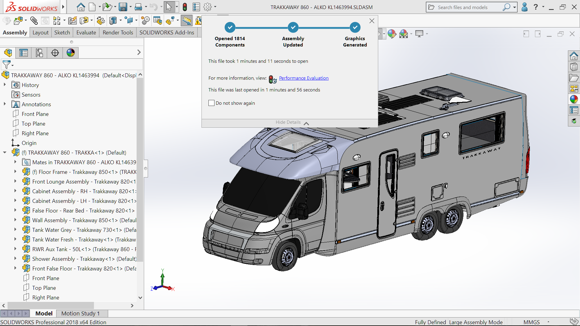
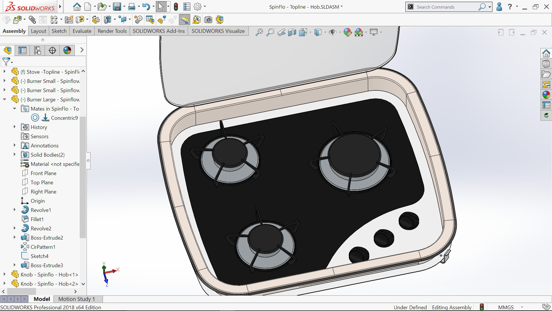
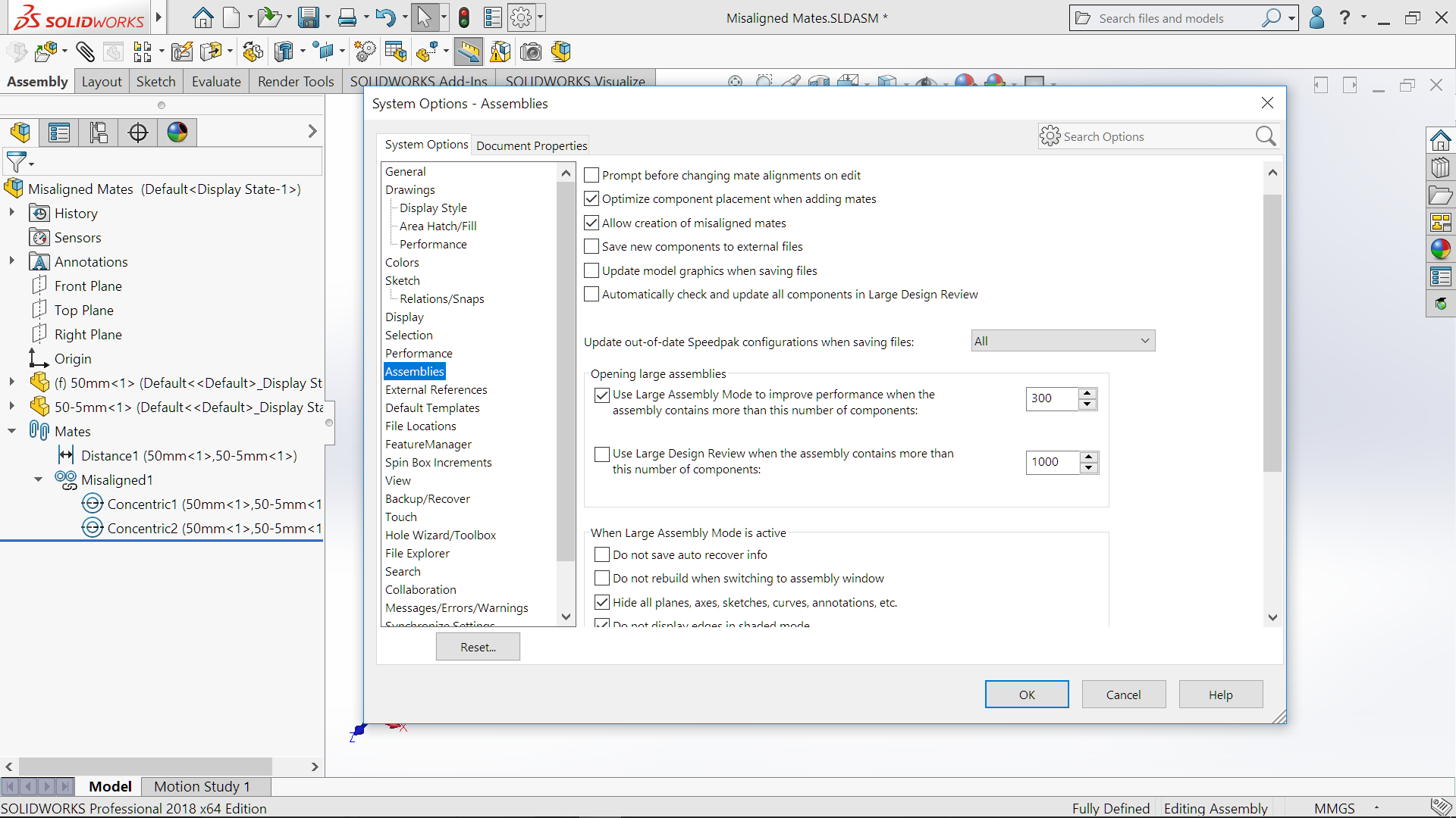 SOLIDWORKS 2018 now provide a couple of enhancements to provide information on the Performance of the Assembly . Or more correctly what is effecting the performance of the Assembly. The first appears when you open an Assembly. The new Assembly Open Progress Indicator provides information on what is happening whilst the Assembly is opening. It provides real time information on how long it is taking for the Assembly to open. Along with showing the number of part and now many have opened. If the Assembly has been opened previously then it will show how long it took to open last time. If the Assembly take more than 60secends to open then the Assembly Open Progress Indicator will remain displayed!
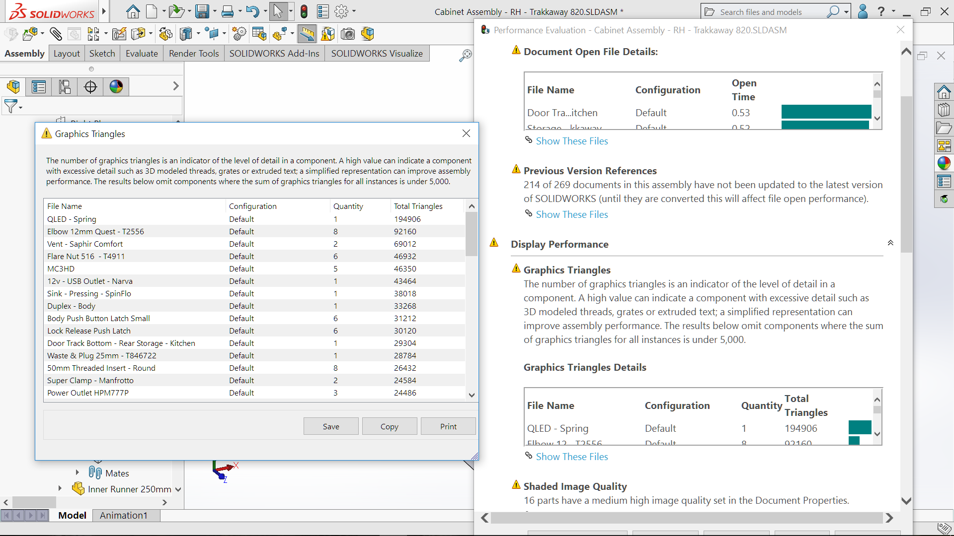
 An interesting enhancement is Assembly Visualization. Accessed via Tools>Evaluate it provides a coloured graphical display of parts which may effect the performance of the Assembly. Columns can be added and display the graphic triangles (level of detail in the part) as well as Opening and Rebuild times of each part. This display provides simple to diagnose data to which parts could be modified to allow better performance.

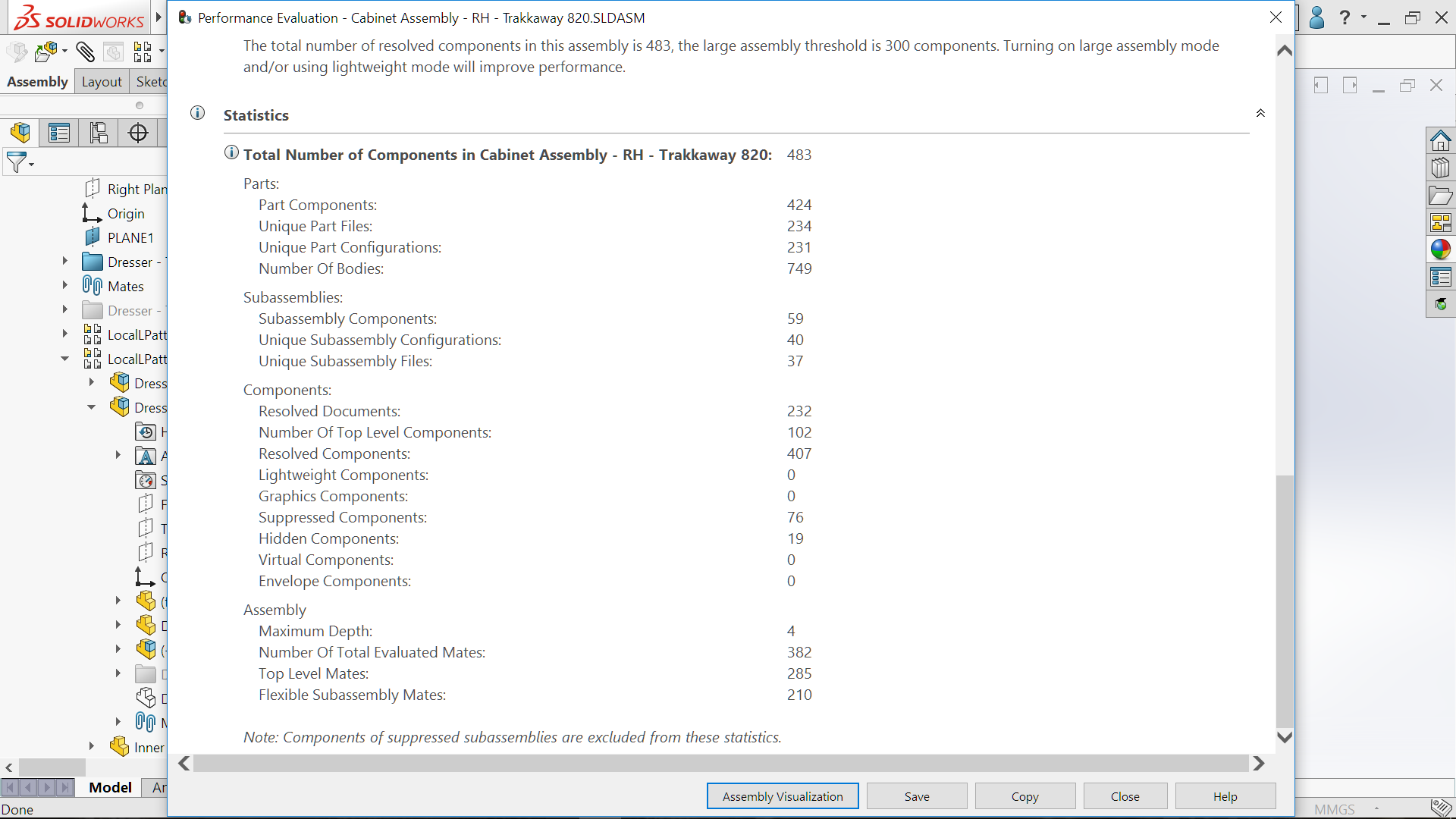
 The Performance Evaluation Tool has been enhanced to provides additional information. The information shown in the Assembly Visualization tool, graphic triangles (level of detail in the part) as well as Opening and Rebuild times is also accessible now with the Performance Evaluation Tool. More statistical information can be accessed for, opening and rebuild times along with the number of graphic triangles
The Performance Evaluation Tool can be accessed from the Assembly Open Progress Indicator, if it remains open, if the Assembly takes longer than 60seconds. The Assembly Visualization tool can be accessed from the Performance Evaluation Tool.
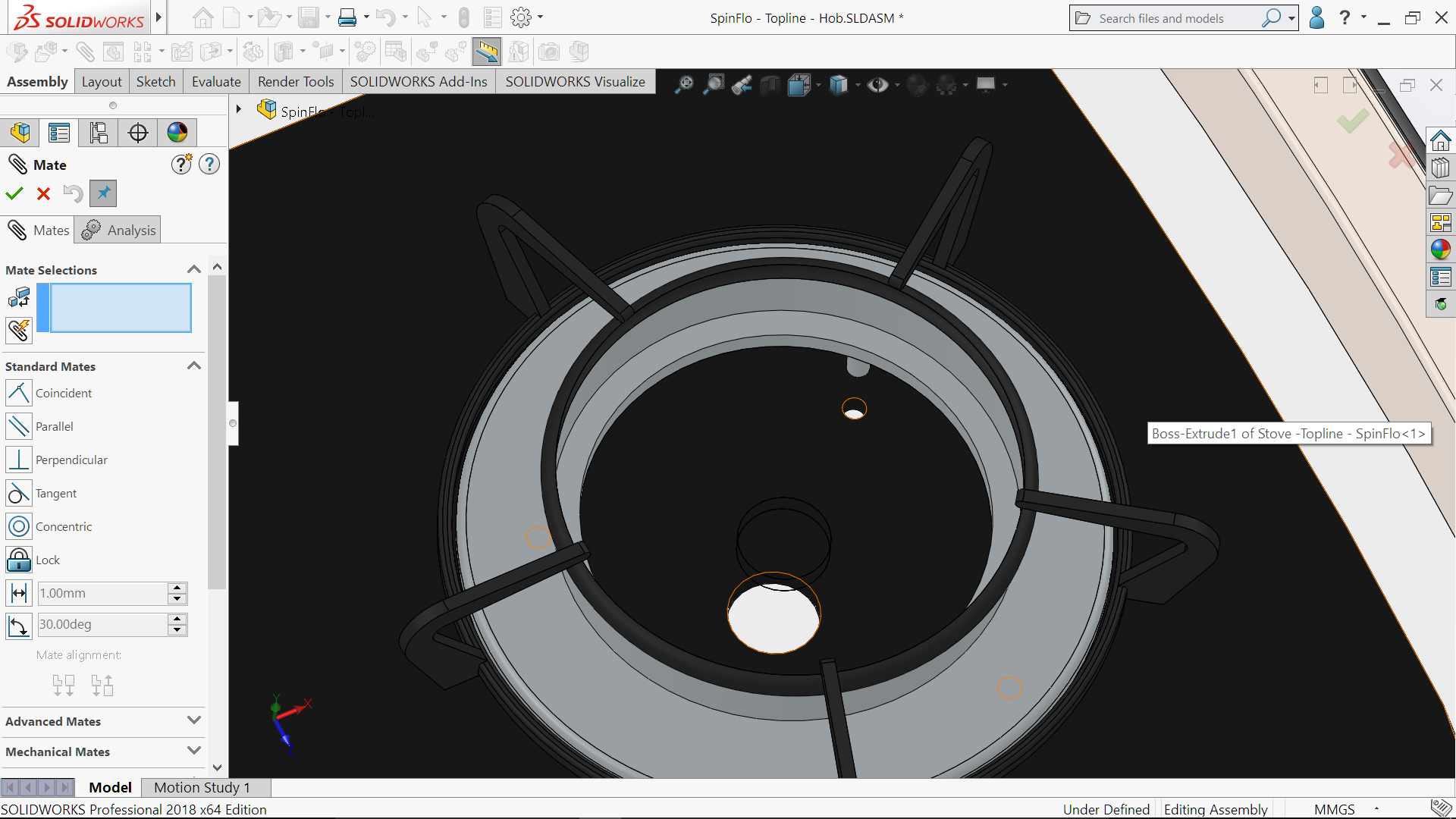
 A simple but nice enhancement to Mates is the Temporarily Hide Faces When Selecting Mates. This will allow faces to be temporarily hidden, so that faces behind them can be seen & selected to allow them to be Mated.
The Mate tool is first required to be select. Then by positioning the mouse cursor over a Face it can be selected with the Alt Key, the face (surface) will be Hidden. As many faces as required can be hidden. Then the Mate can be created as normal. Once the Mate has been created the temporary hidden face(s) will then once more be shown.
 Linear Pattern now have the ability to add, rotation to a linear pattern. Whilst in the Linear Pattern FeatureManager, when selected, the Rotation Instance opens the options to select the entity for the rotation and the amount of angle. It retains all the existing option including the ability to skip a linear patterned rotated instance. This is quite the time saving enhancement!
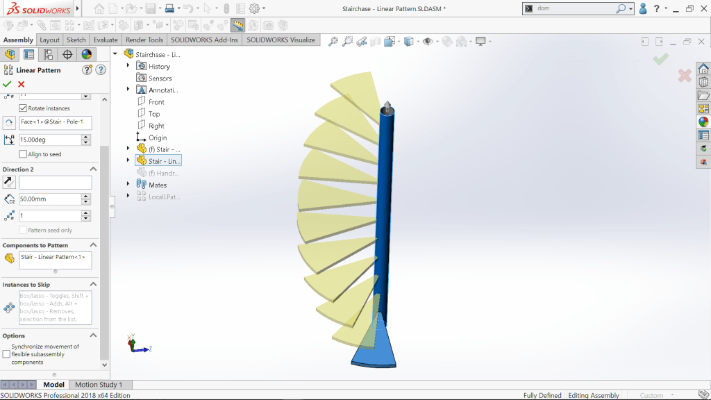
Adding Explode lines to an Exploded Configuration was once a manual task. SOLIDWORKS 2018 has added Smart Explode Lines. Now it is just a simple matter of RMB on the Explode configuration and selecting Smart Explode Line.
 The line trace is added referenced to the bounding box centre, as the default. The Exploded line can be manually re-positioned.
 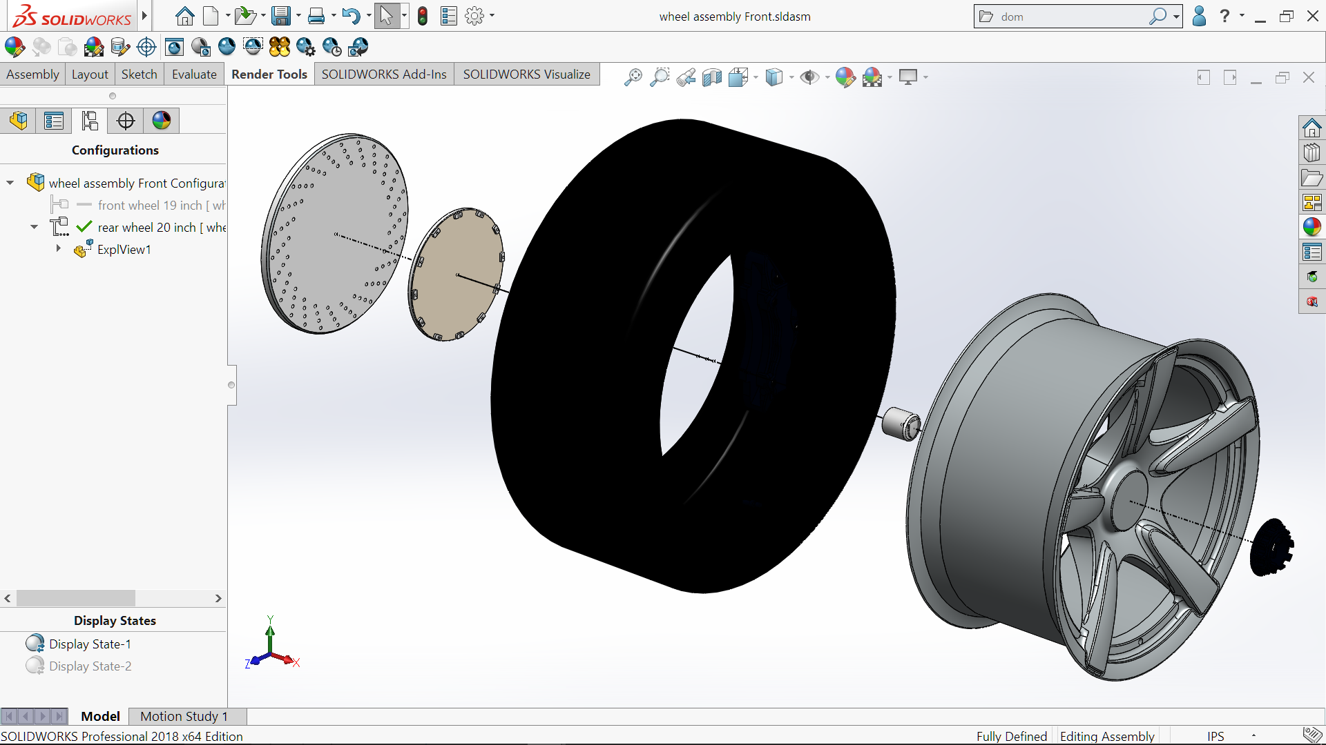 There are some nice enhancements in the area of Assemblies with SOLIDWORKS 2018. In addition to the enhancements & new features SOLIDWORKS 2018 also sees improvements in performance with quicker opening times of Assemblies. As this is a targeted area for improvement, it will be interesting to see what will happen with further development of Large Assemblies.
See more in SOLIDWORKS 2018 – Easier Assembly Builds

Leave a comment