
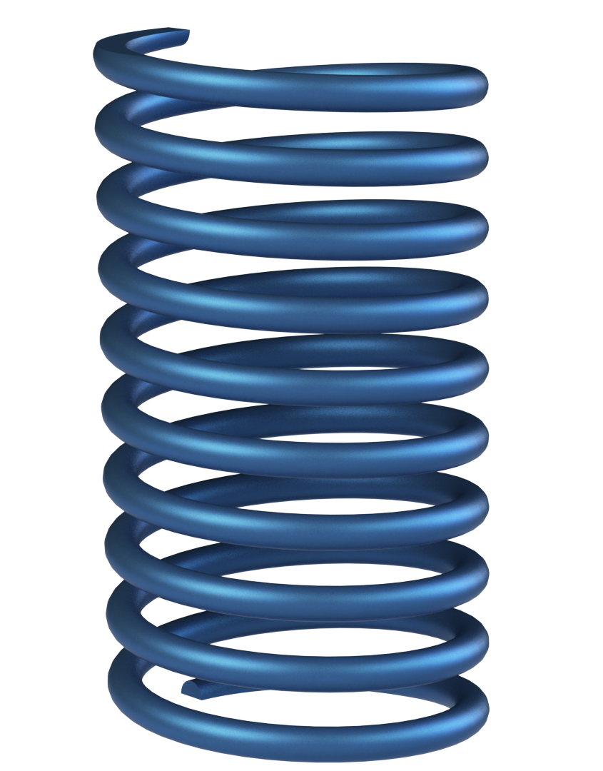
 I would take a good guess that the first thing that many model after they have learned basic modeling in SOLIDWORKS would be a spring!
You have worked out the basics of the Swept Boss feature and have discover the Helix tool, slightly hidden under Curves.
Create the Helix, sketch a circle and Sweep it along the Helix. Instant Spring, simple, nice!
Let’s be honest, what’s not to like about springs!
Before the Thread feature was introduced in SOLIDWORKS 2016, most, I suggest, once they have conquered the spring would have moved onto creating threads.
 What is the point of having a Swept Cut feature if you are not going to cut some threads with it? Again, it is a straight forward creation of the Helix and the profile to be Swept along it.
But what if you require a non-circular helix? Maybe a better description maybe a non-continuous curved helix! By definition I think it still qualities! “tangent line at any point makes a constant angle” What if you require something like this?
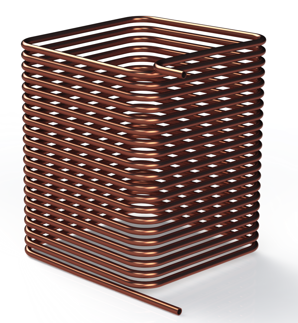 Like all things in SOLIDWORKS there would be a few different ways to create this style of component. For those who have not used Surface tools, this will be a good introduction, to the use of a few of the basic Surfacing features.
The basic features of Surface tools work in similar ways as Solid modeling. So an Extrude acts the same regardless of if you are using a Feature or a Surface.
Lets take a detailed look at how to create the above non-circular helix!
Start with a sketch of the finished shape of the non-circular helix profile. In this case a square with filleted corners. Extrude Surface the sketch to the required height.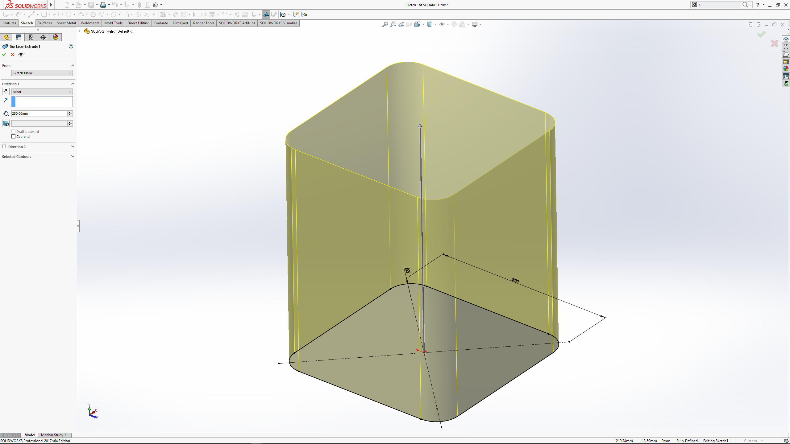
 On the same plane as the profile sketch, sketch a circle for the diameter of the Helix. This should be kept inside the shape of the profile sketch. Create the Helix. In this case to the height if the Extrude Surface. I tend to use Height and Revolutions but it matters little to how the Helix is defined. For this design I set the start angle to one of the main planes. Your design would determine this from model to model.

 Create a sketch on the Plane which intersects the start point of the Helix. This sketch is a horizontal line from the start point of the helix that extend out past the created Extrude Surface. Use the Swept Surface with the line as the profile and the Helix as the Path. Ensure that the profile of the sweep fully extends outside of the Extruded Surface.
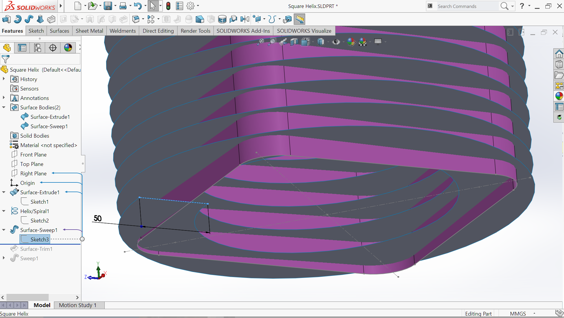 Select the Surface Trim feature and use the Extruded Surface as the Trim Tool, select the Swept Surface (outside of the Extruded Surface) as the section to be removed. Once the Swept Surface is trimmed the Extrude Surface is no longer required and can be hidden.
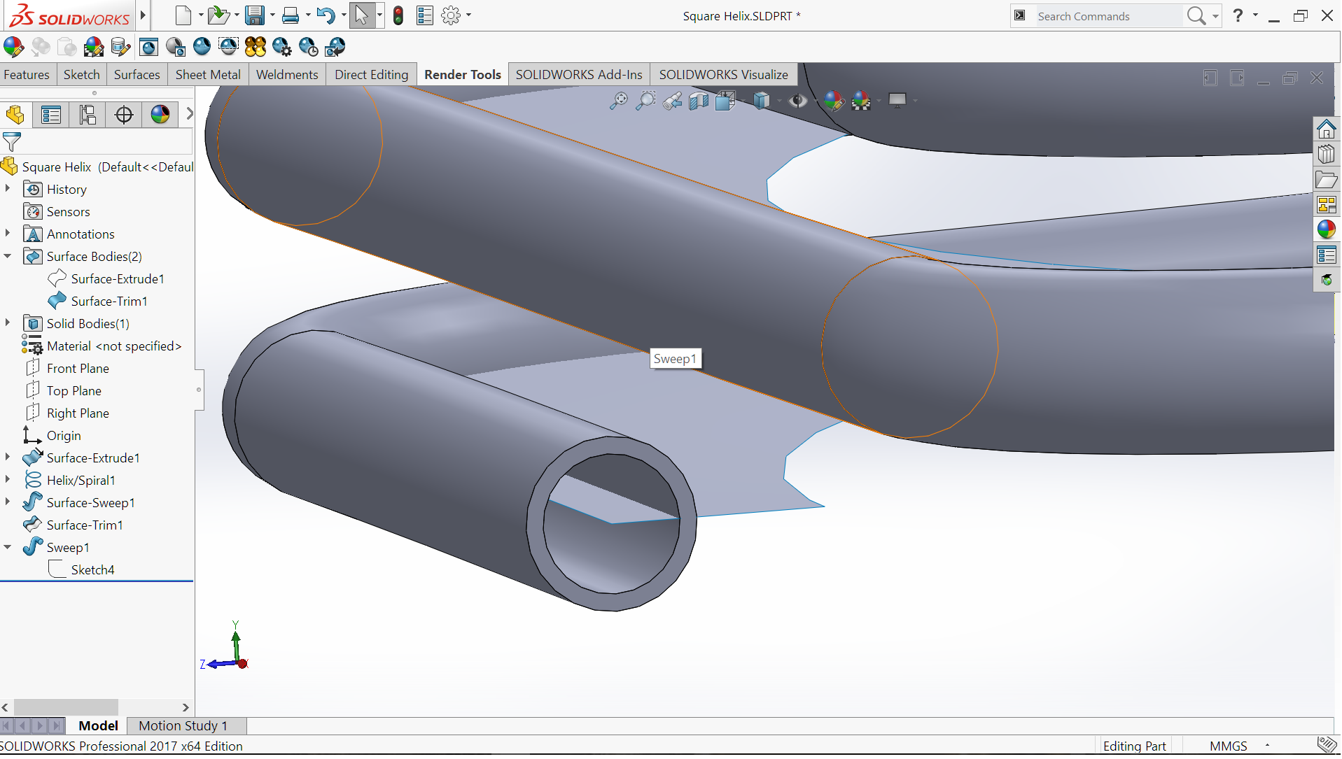
 Create a sketch of the required profile to be swept along the created non-circular Helix. In this case a couple of circles for the profile of the tube. Using the Swept Boss, select the sketch as the profile and the outer edge of the Swept Surface (Open Group) You will see some people create a 3D Sketch by selecting the outer edge of the Swept Surface, then Convert Entities but this is an unnecessary step. Hide the Swept Surface and as simple as that, you have a non-circular helix swept part !
 By using these Surface features it is a simple process to be able to create the non-circular profile. This technique is not restricted to only geometric profiles. As shown with this next example.
With this model we can start with a simple sketch and use the Revolve Boss to create this shaped.
Creating a plane at the require height in which to position the Helix for the spiral cut.
The Helix is created via the normal method of a sketching a circle on the created plane. The circle again is dimension to fit inside the smallest radius of the revolved shape.
Once more I used the Height and Revolutions to define the created Helix.
 The Swept Surface is created as before by a horizontal sketch as the profile, with the Helix once more as the Path.
  I used the Trim Surface method using the face as the Trim tool.
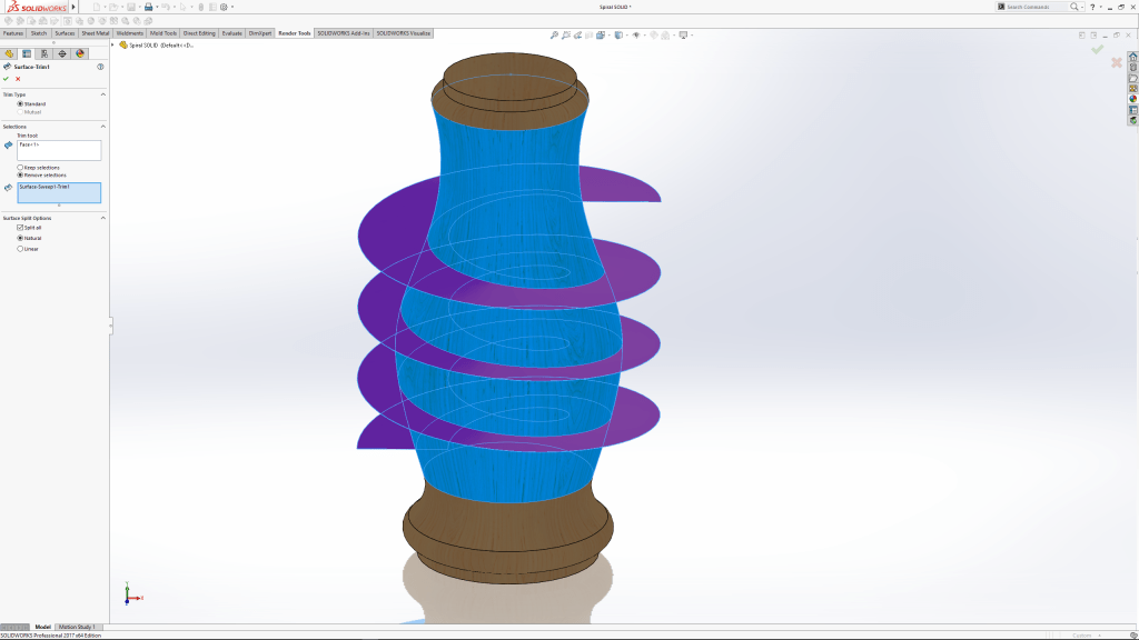
 Once more create the sketch on the required plane to provide the profile to use with a Cut Sweep.
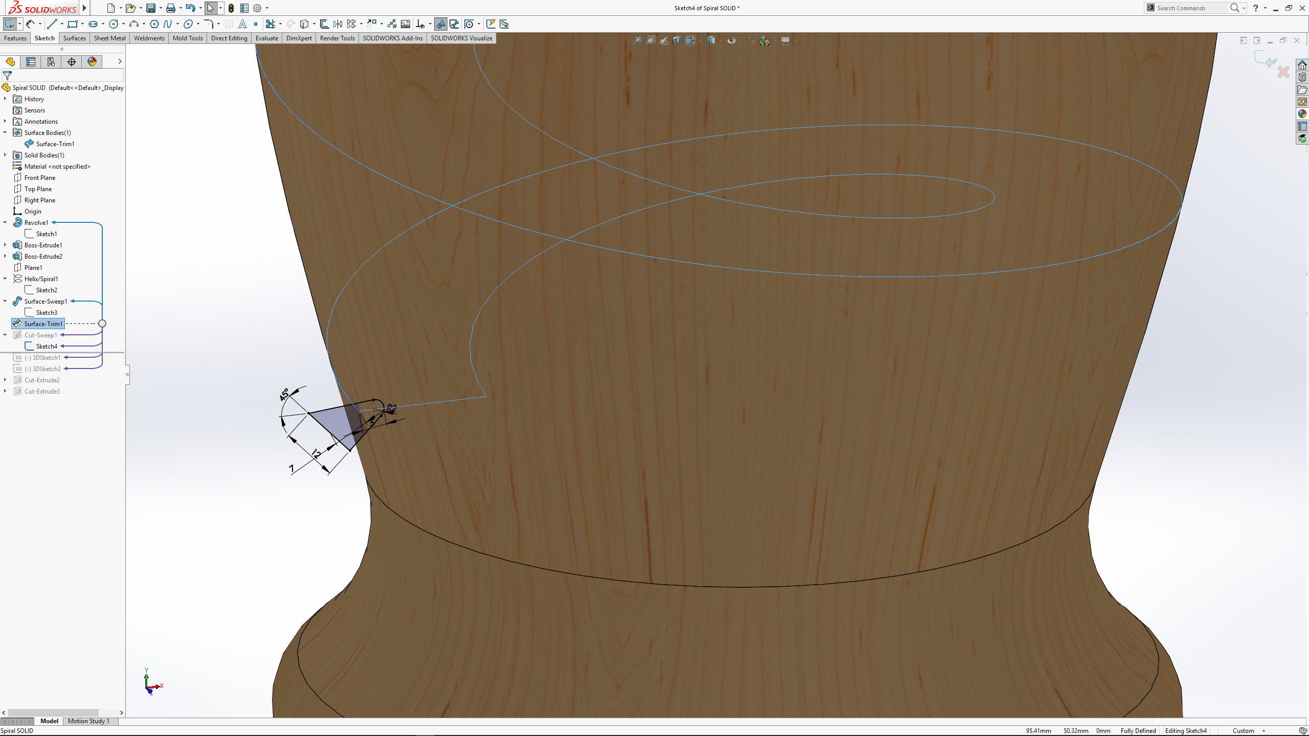 This leaves the the spiral cut with a square ends. A 3D sketch tangent to the helix gives the direction for a cut extrude to taper the cut to the surface.
This simple surfacing technique is a handy trick for creating path’s on many a irregular face.
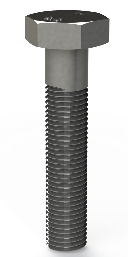
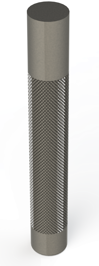 Lets finish by take a look at a conventional helix’s and a common request seen on the SOLIDWORKS Forum. How to create knurling!
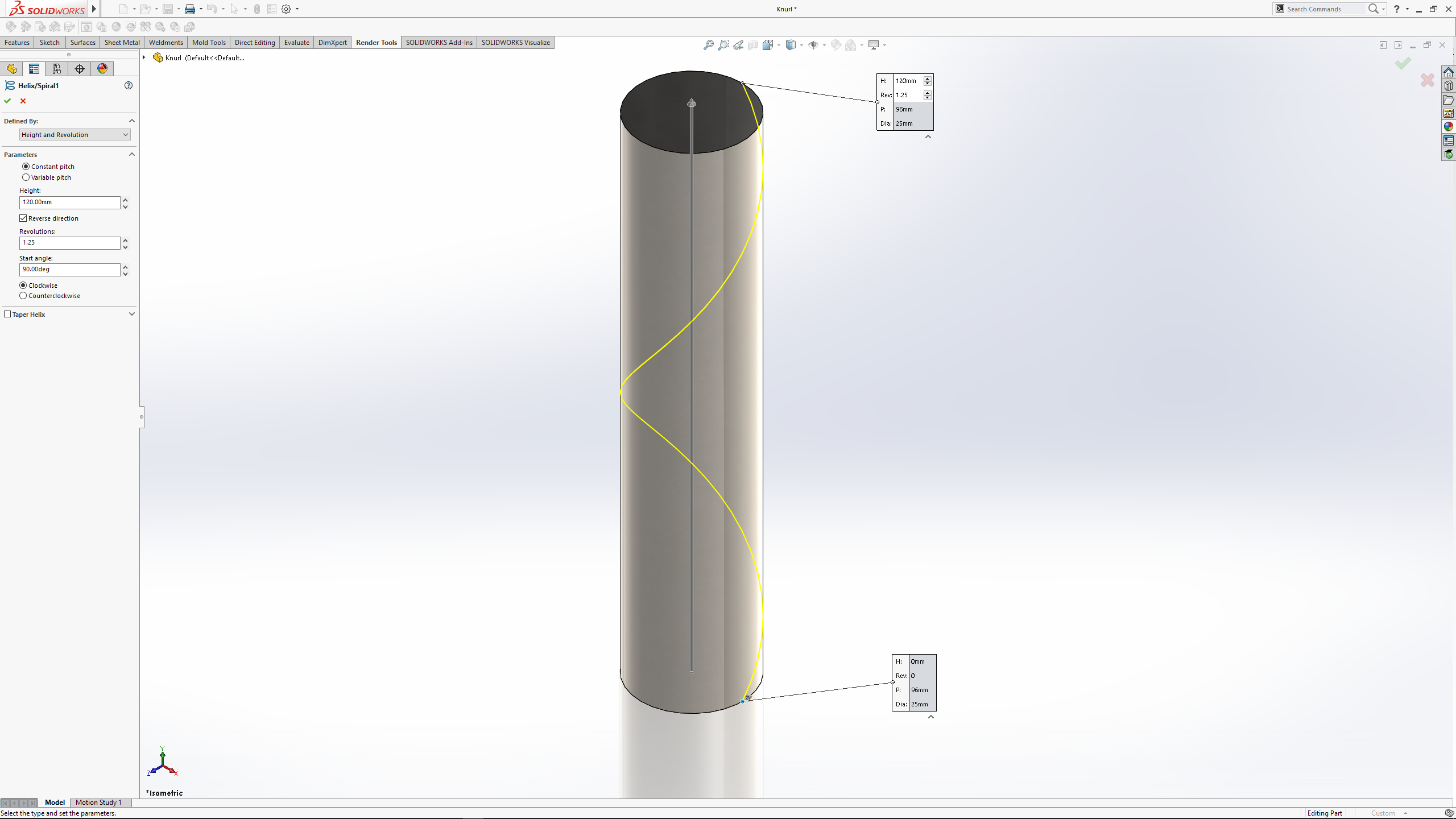
After creating the Extruded rod, start a sketch on the end face or plane. Select the end face or edge and use convert entities to create the sketch for the helix. Use the sketch and create the helix. There are formulas for knurling but if you are creating in the model I suggest it is more for looks or 3d printing more than complete accuracy.
For this model I used 1.25 revolutions over 120mm length.
I created a new plane perpendicular to the helix for the profile to be used for the Swept Cut.
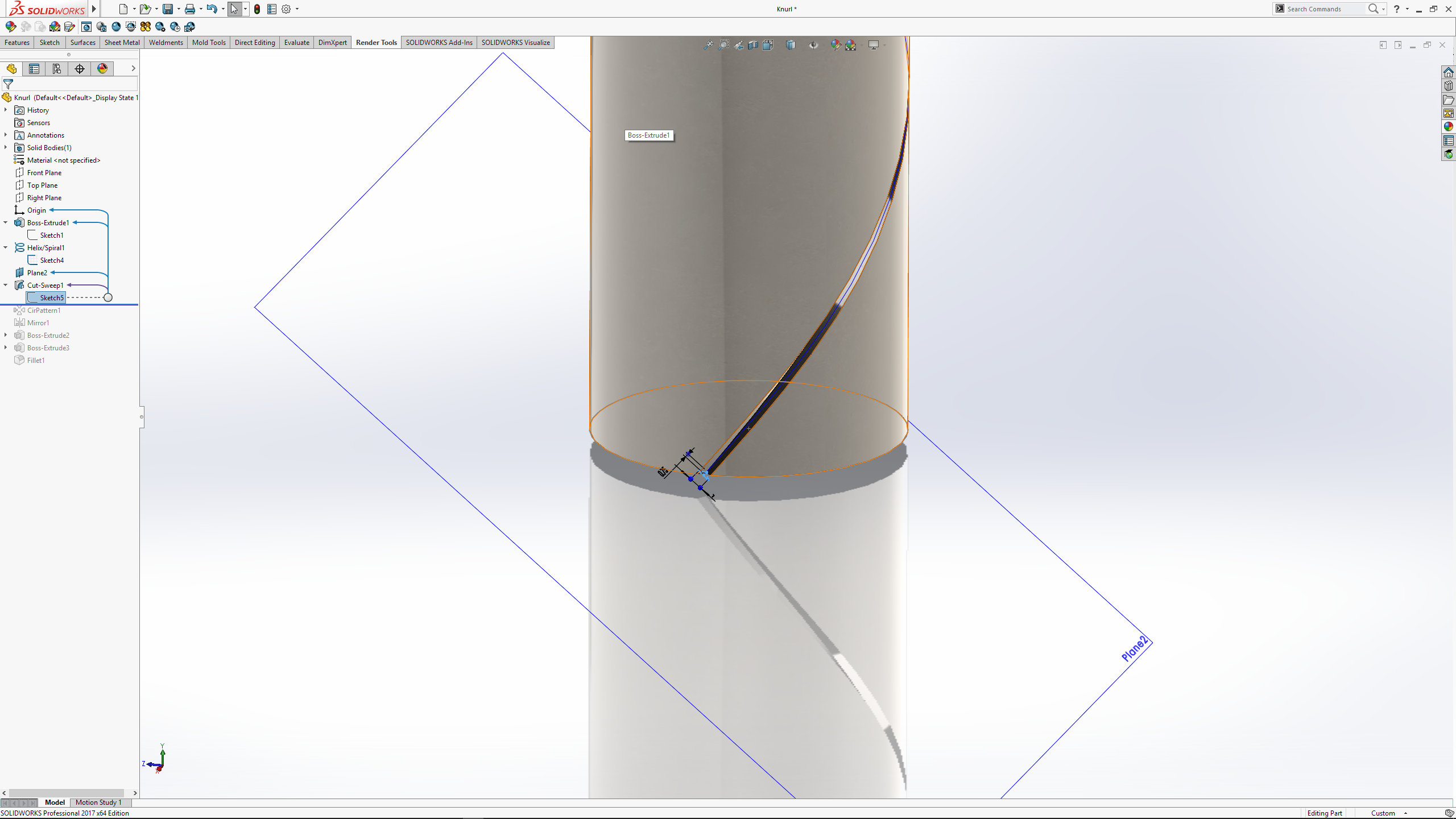
 Make a circular pattern with the Sweep Cut as the seed. I this case I used 40 instances, equally spaced around 360°.
 Mirror the Circular pattern to complete the knurling.
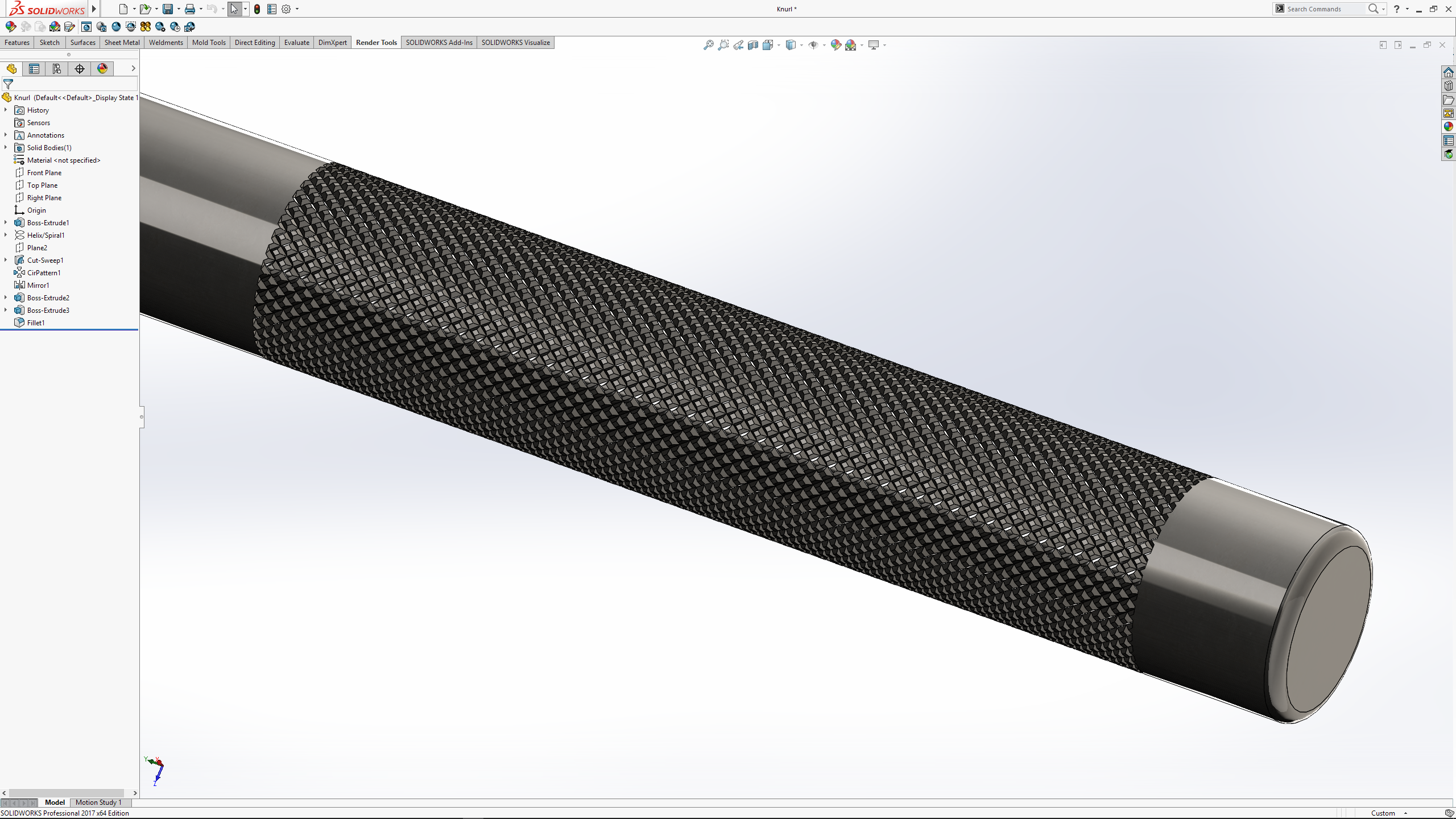 Although it is simple process (and a great look) it is not something that I would recommend. Mirroring the Circular Pattern to create the knurling is a resource killer. For this small pattern the rebuild time is 352 seconds, of that the Mirror took 98% – 345second.
For more details download the attached files used above.
SOLIDWORKS 2017 PARTS – Download
Parasolid PARTS – PARASOLID

Leave a comment