
I’ve never been a big user of Weldments. Much of that has had to do with SOLIDWORKS and it’s Sheet Metal tools. This allowed us to not only move away from “cut & weld manufacture”. It also opened up greater access to the Sheet Metal industry with their laser cut and computer folding capabilities.
Every now & then I find a project that is best suited for the use of Weldments. One came up the other day which was then I discovered that I hadn’t used Weldments before on that computer!
Weldments use sketch “Profiles” which are swept along sketch “Paths” to create a single multi-bodied part. Or more correct and by SOLIDWORKS own definition “Sweeping a predefined sketch along a user defined path” It is by that very definition that we have to start with, to be able to use Weldments. We first have to find or create the “predefined sketch” By default there are a very limited number of profiles available when “Structural Member” are selected However SOLIDWORKS has available an extensive range of profiles from a number of Standard. These are accessible via the Design Library>SOLIDWORKS Content>Weldments. These can to be downloaded: (Ctrl+select).
  Once downloaded and unzipped the Folder needs to be placed within a “Weldment Profiles” Folder. By default this is:
C:\Program Files\SOLIDWORKS Corp\SOLIDWORKS\lang\english\weldment profiles. Personally I wouldn’t place the profiles there. This is a folder which will be replaced with each install/ reinstall. It is preferable to create a Folder on your local or network drive. This additional location can be added via: System Options>File Locations>Weldment Profiles
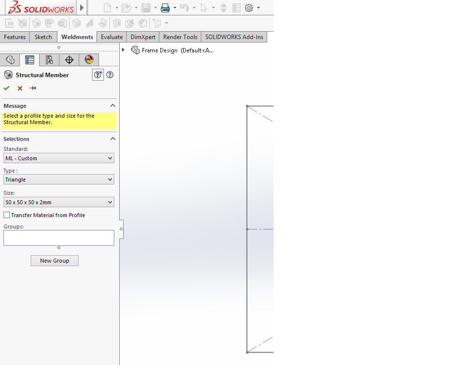
Once the folder is added the profiles can be selected by Standard, Type and Size required However you are not restricted by the available profiles. Any closed sketch can be used to create a Library feature. The sketch needs to be Save As> Lib Feat Part (.sldlfp). Importantly you first must select/ highlight the sketch otherwise the Library feature will be empty on saving. It should also be noted that the origin of the sketch becomes the default pierce point on to the path
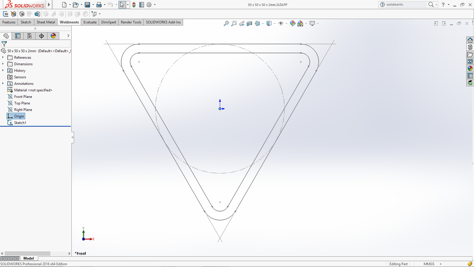 But here is the real trick! It is how you save the sketch which is important as this is how it will be accessed as a Structural member. The sketch name will be shown as the “Size”. It must be in a sub-folder, who’s name will be shown as the “Type”. That sub-folder will be in a Folder , who’s name will be shown as the “Standard”.
 There is of course an exception to that folder structure! First introduced in SOLIDWORKS 2014 was the ability to use configurations with the sketch that was to be used as the profile
So lets have a look at how that works. RMB (Right Mouse Button) on a dimension. You may first have to RMB on Annotations in the Feature Tree as select “Show Feature Dimensions” On the context tool bar Select “Configure Dimension”  The Modified Configuration table will open. LMB – double click on each of the other dimensions will add the additional columns for those dimensions. Name the configuration and change the dimensions as required.
 This can also be achieved using Design Tables. As the process to create a Design Table is a simple one.
 Insert>Tables> Design Table. Then select – Auto Create. The Design Table Excel sheet will be created with the required columns and opens directly in the graphics area. Create additional configurations and change the dimensions as required. The use of Design Tables has the advantage of being able to copy & paste or insert from other tables, such as manufactures specifications.
Now when saving the sketch as a Library feature you will still need to save in a Folder for the “Standard” however the configured sketch will become the “Type” (and will show as a “Configured” profile) The configurations will become the “Size”.  With the predefined profiles now in place at least your ready to start creating a Weldment part!

Leave a comment