
It all started with what was a simple question posted on the SOLIDWORKS Forum. (or access via the My.SolidWorks website)
This was the model posted. It showed the issue trying to use the “Wrap” Feature to achieve the result! I can understand the thought process on why you would try this. If you were to manufacture this by hand. There would be a good chance that you cut a paper template and “wrap” that around the tube! The problem I see was based around the Sketch! For me it looked difficult to control and I had to think about how you would control the relationships between the points. I guess you could use equations to control the circumference if a change in tube size was required! There were a few suggestion to get around the problem shown including using the Flex feature. However none really got around the issue of the sketch complications.
But I thought how would I approach this.
This is how I started (and I’ll try and cover my thought process) as I go along! I started by creating two additional planes. Sketched a circle (tube diameter) on the Mid Plane. Sketched a pair of construction lines which were coincident to the circle. (more on those below) At this stage I set out to model like I was manufacturing, so I Thin Extruded the circle to create the tube.
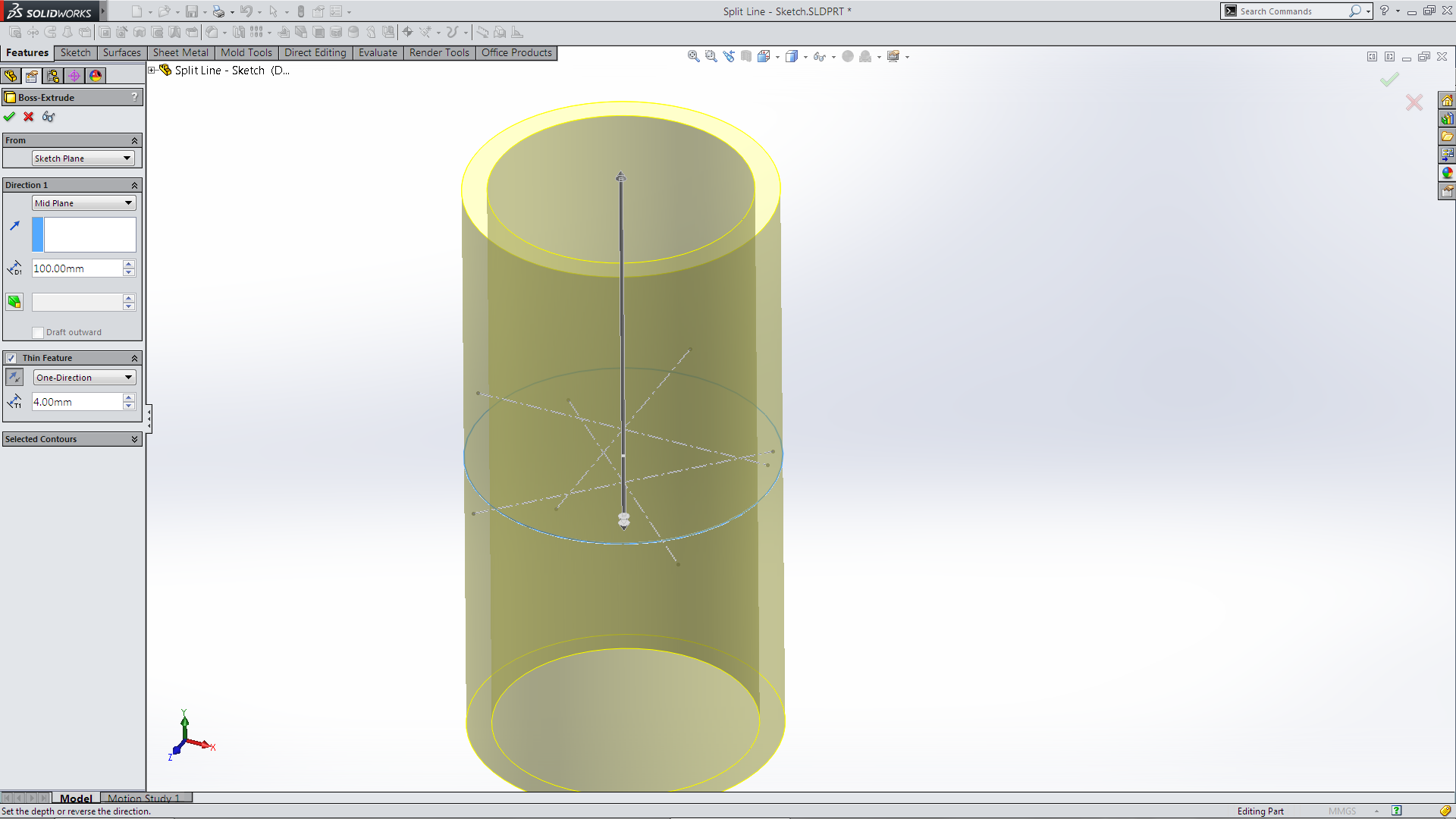 I now used a feature that I have only ever seen shown before but never used – Spline on Surface. The Spline on Surface sketch tool is not standard on the sketch tool bar. I accessed by selecting 3D sketch, Right Mouse Button the viewport which brings up the Sketch Flyout toolbar. Or if you place the Spline on Surface tool on the toolbar by selecting it, it will automatically start the 3D sketch.
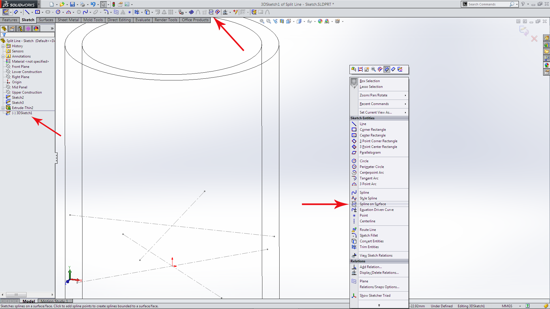 The created construction sketches and the placement of the Planes divided up the cylinder to the require eight segments (which meant I didn’t have to think too hard). It was now just a matter of selecting each of the end points.
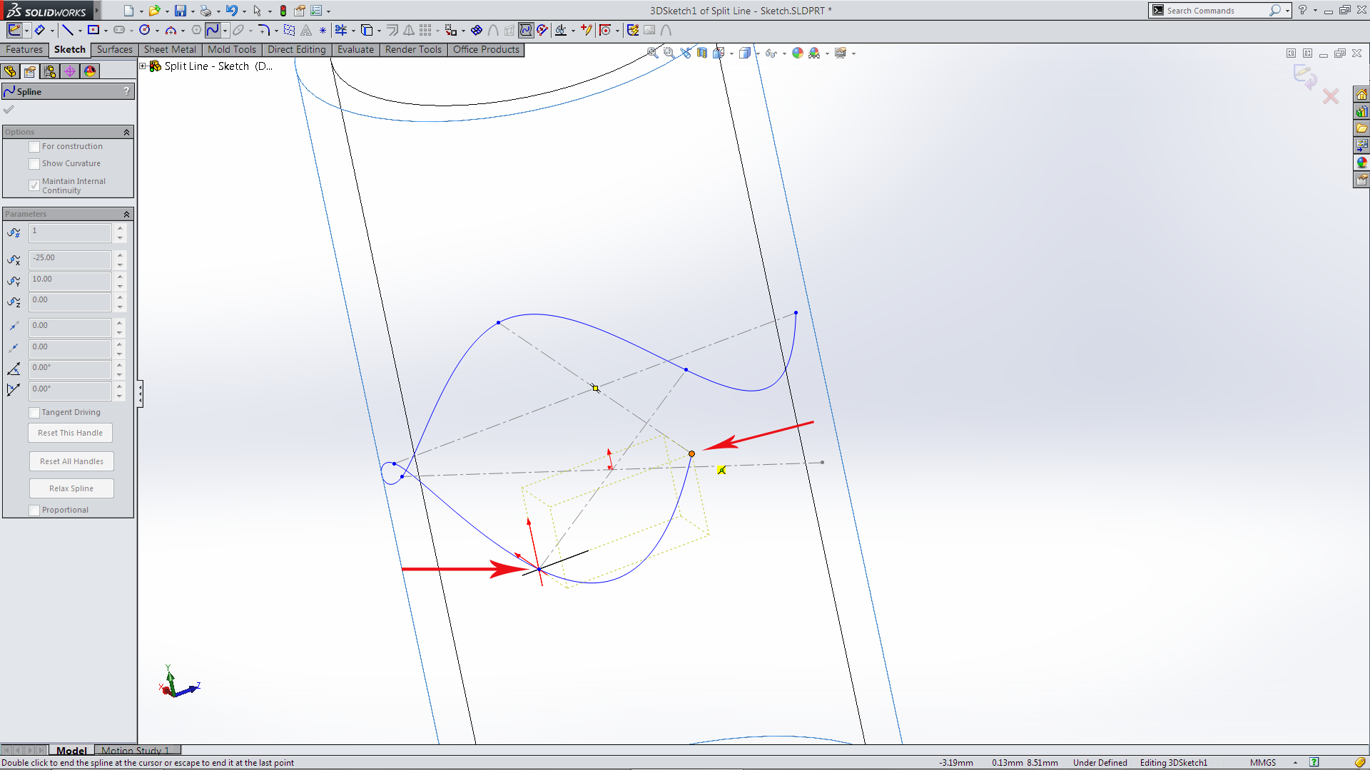 Which creates a fully defined sketch on the surface of the cylinder.
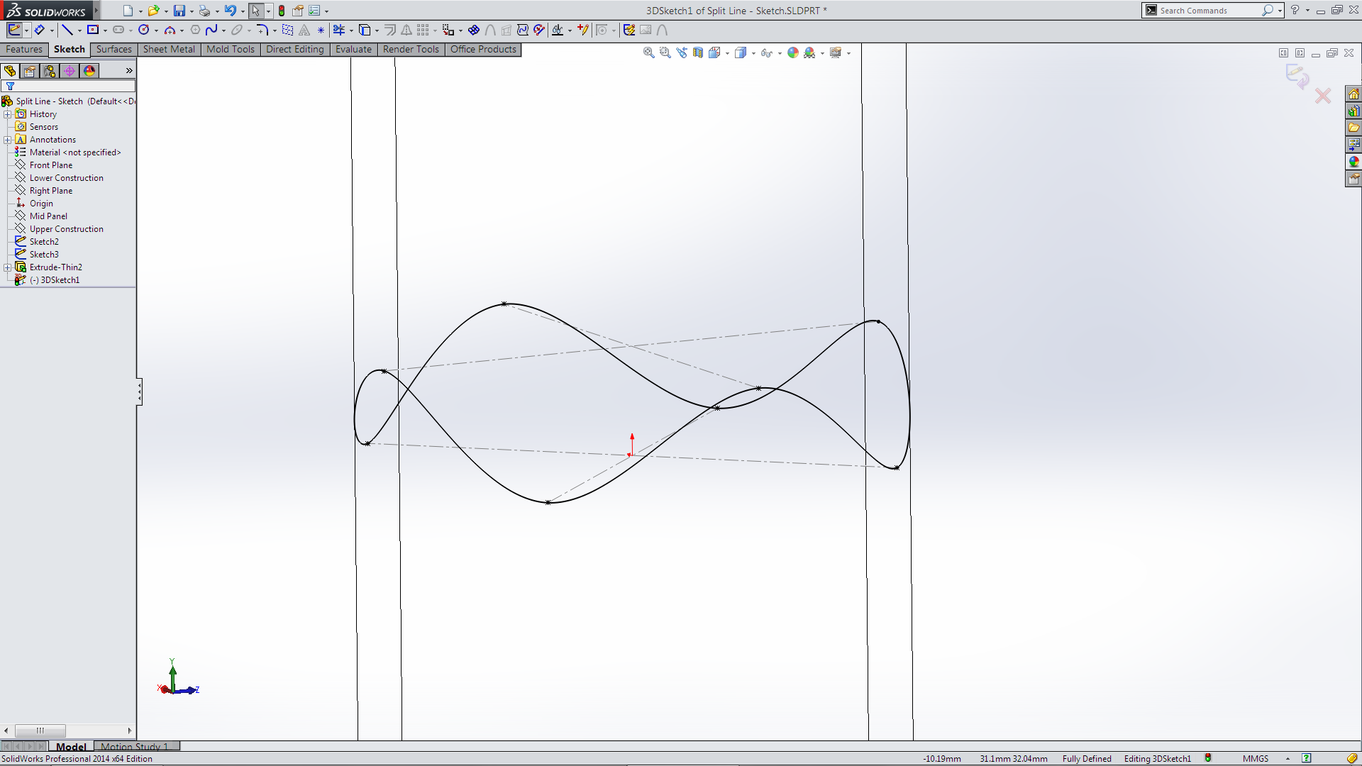 So far so good! Still in modelling like I manufacturer mode. I thought how would I cut it. My first thought would be a CNC tube cutter. So based on that I created a rectangle sketch on one of the planes. intersected one of the end point then revolve to create a rod. (Unselect-Merge Results to create two bodies, more on that below)
 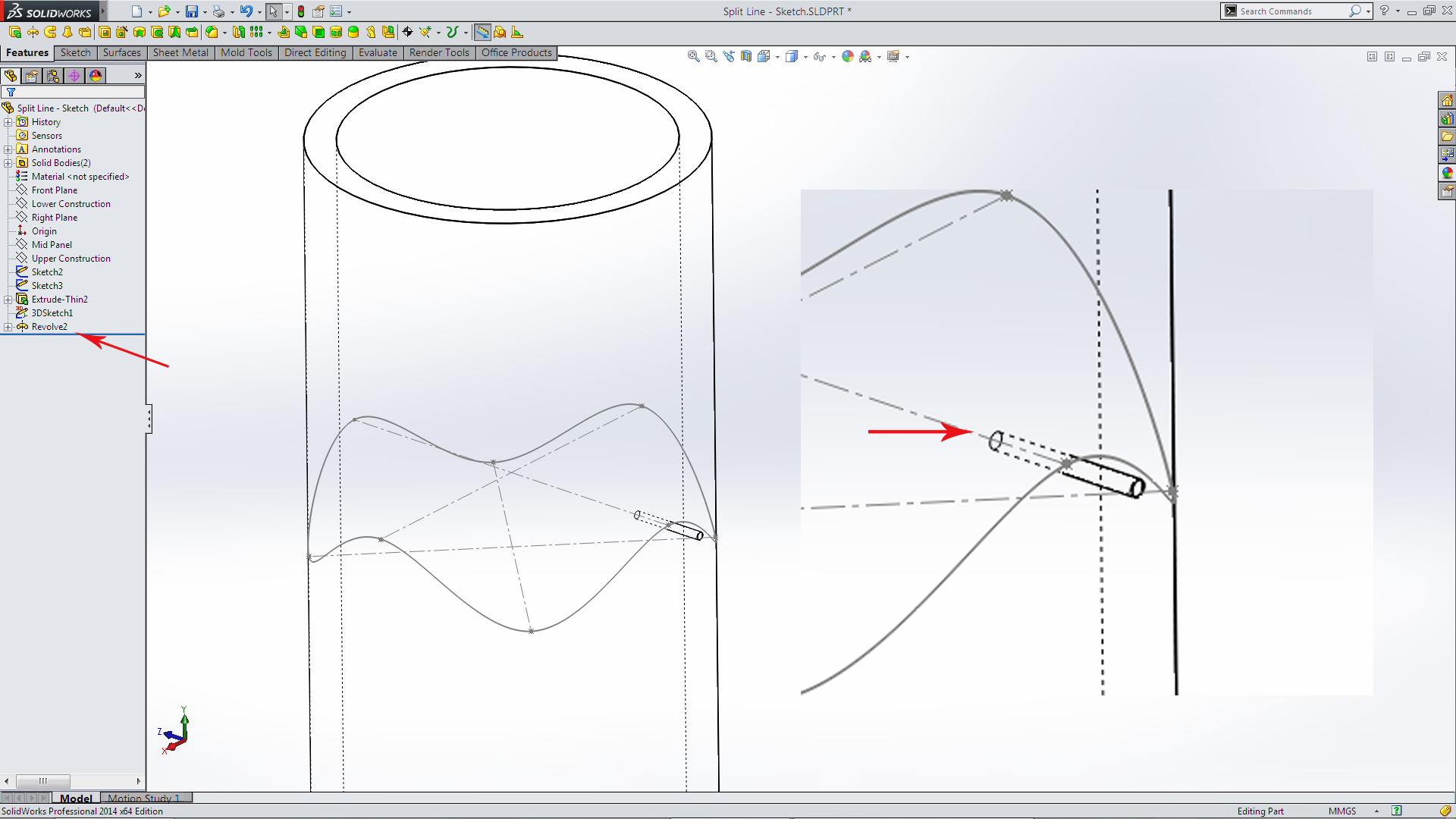 I don’t use the Swept Cut all that often and by chance have just discovered that you can cut with a Solid! (Who would have thought that!) It has limitations. The solid has to be convex, revolve or an extrude (rod) and a separate body (thus the unselected merge result)
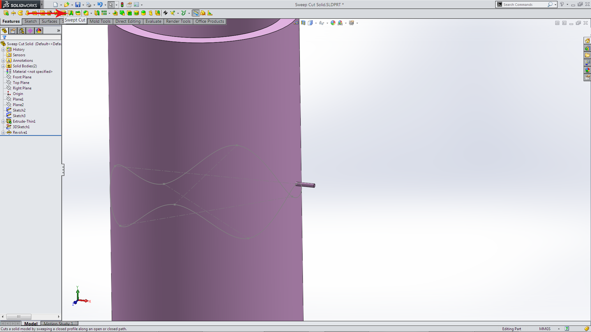 Select Cut Solid Body, select the Solid body (revolve) and the Path sketch
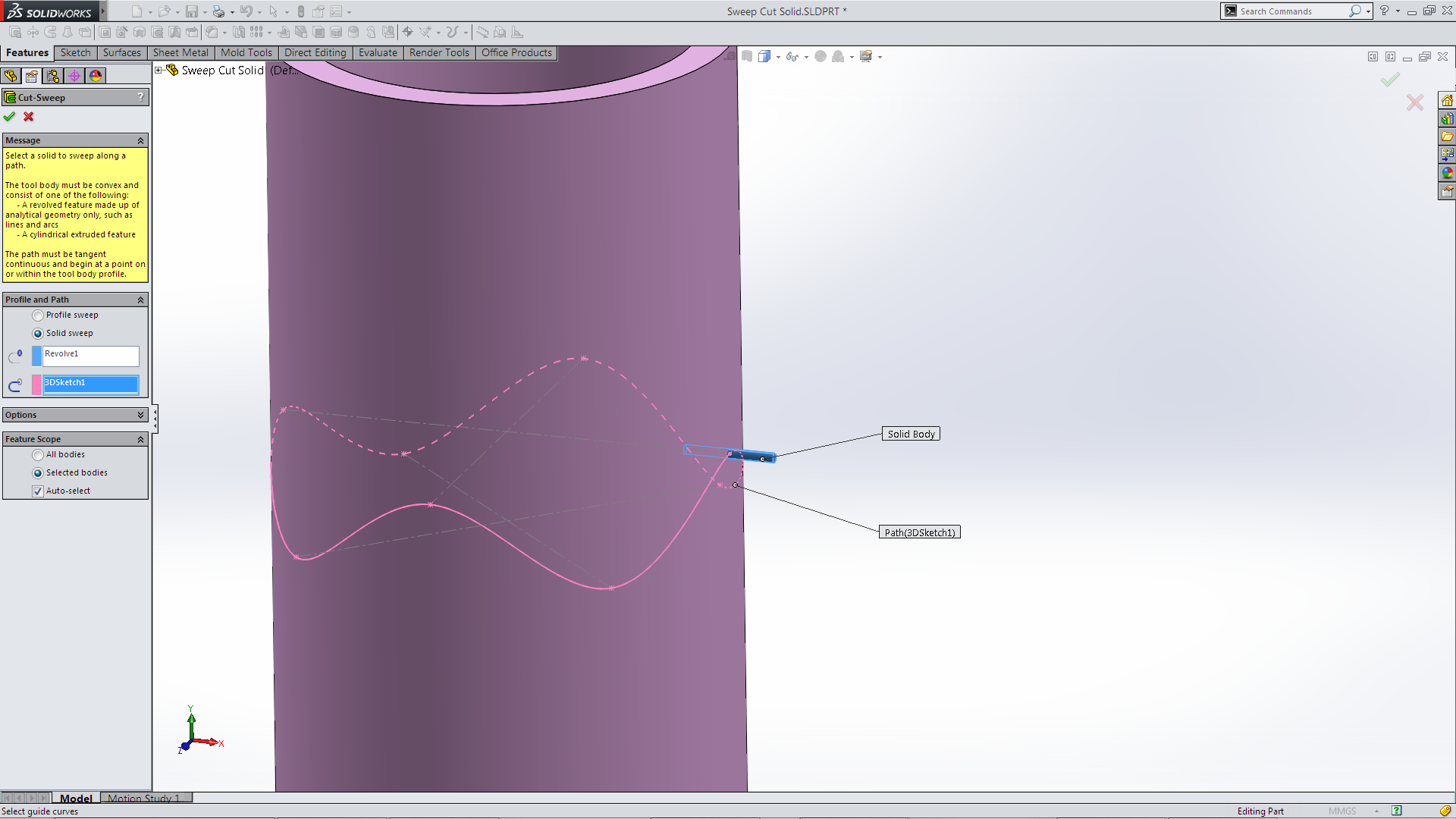 Select Preview and slightly panic!
 It is at this stage I look in the Options – Orientation/ twist type and Path Alignment type. Selecting Path alignment type – minimum twist.
 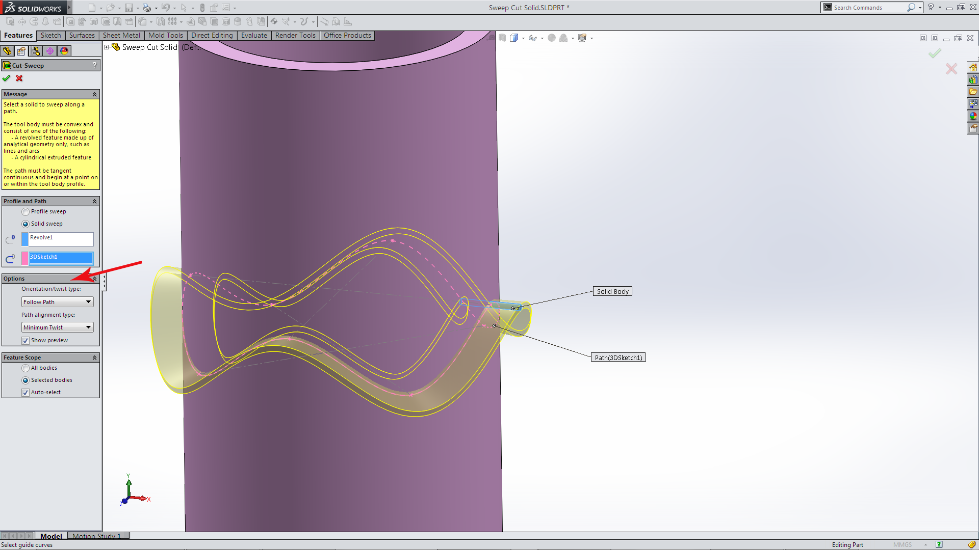 When it cuts it will create two bodies. Select which body to Keep from the Keep Bodies dialogue box.
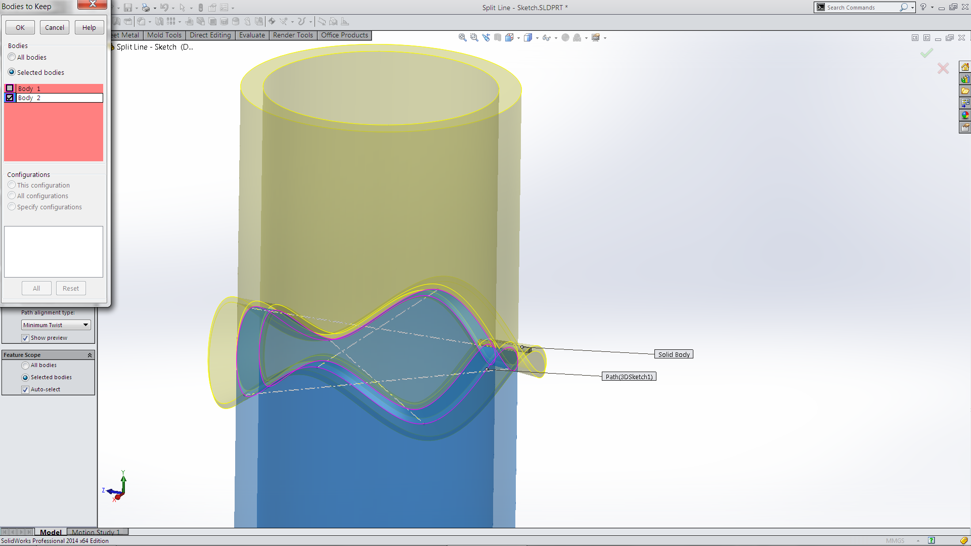 The created Part! Although it looked correct the valleys in the cut were not horizontal.
 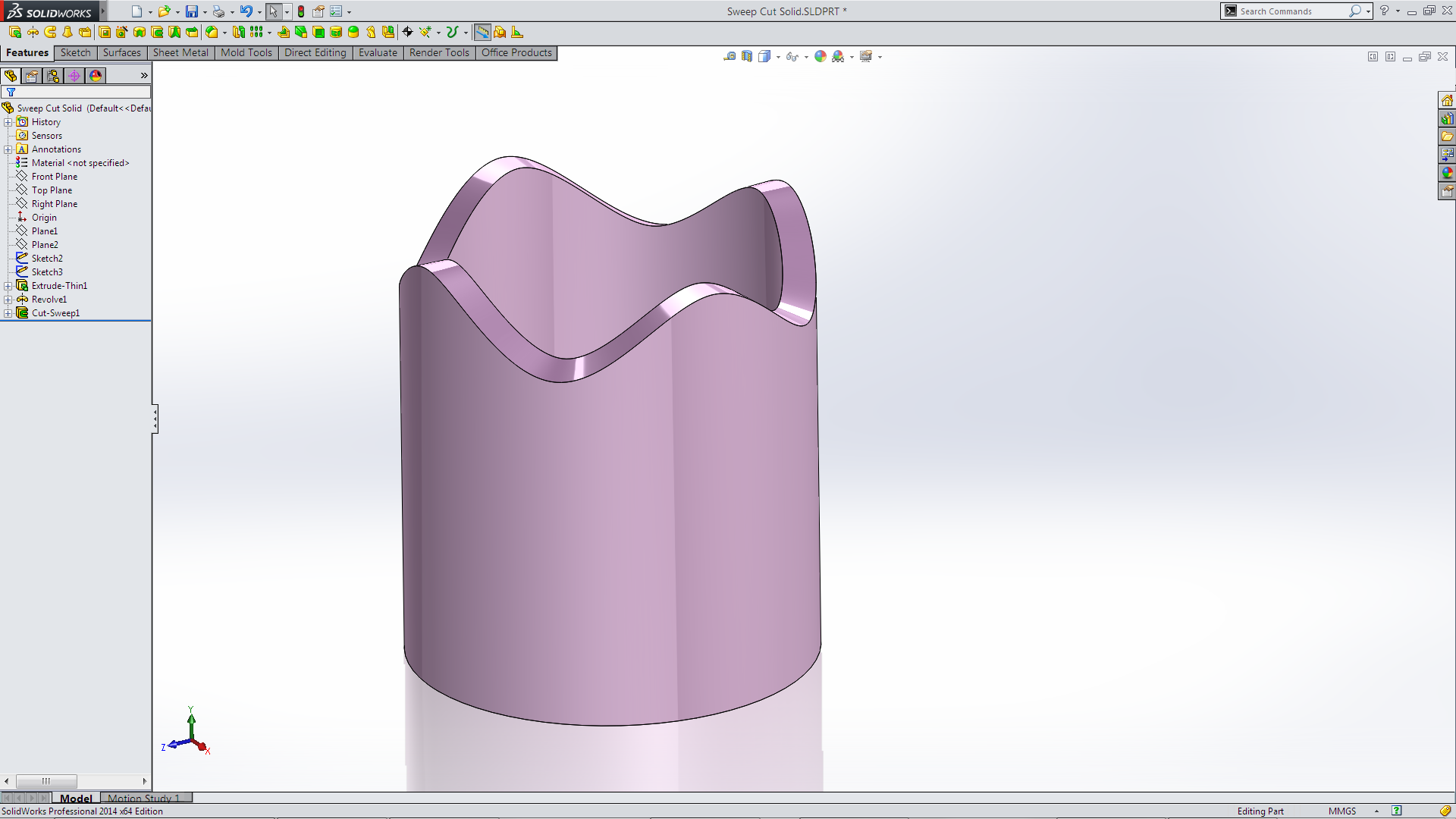 At this stage I abandoned the manufacturing mode of thought and switch to the modelling mode of thought! Another tool I use rarely is Split Line which is found on the Curves tool bar
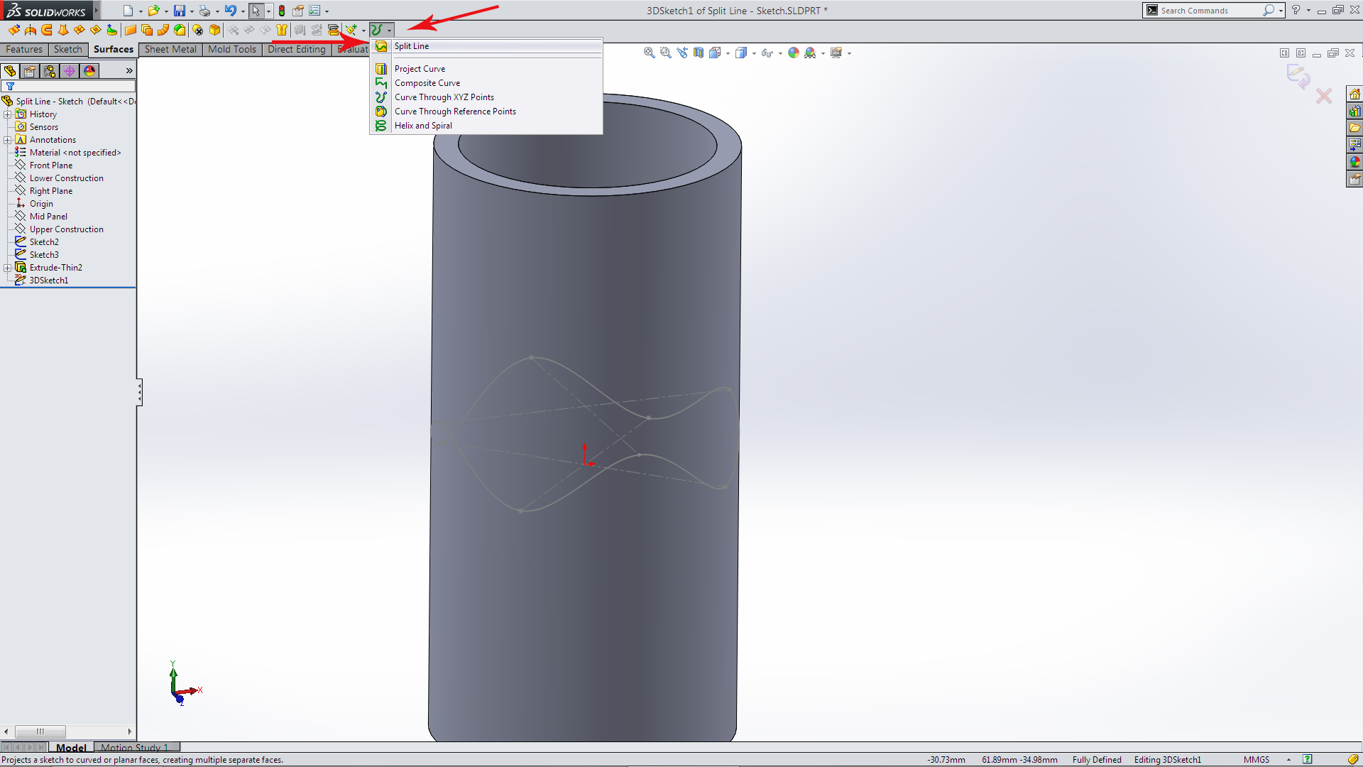 The Split Line tool splits just the surface! So I Split both the inner and outer surface.
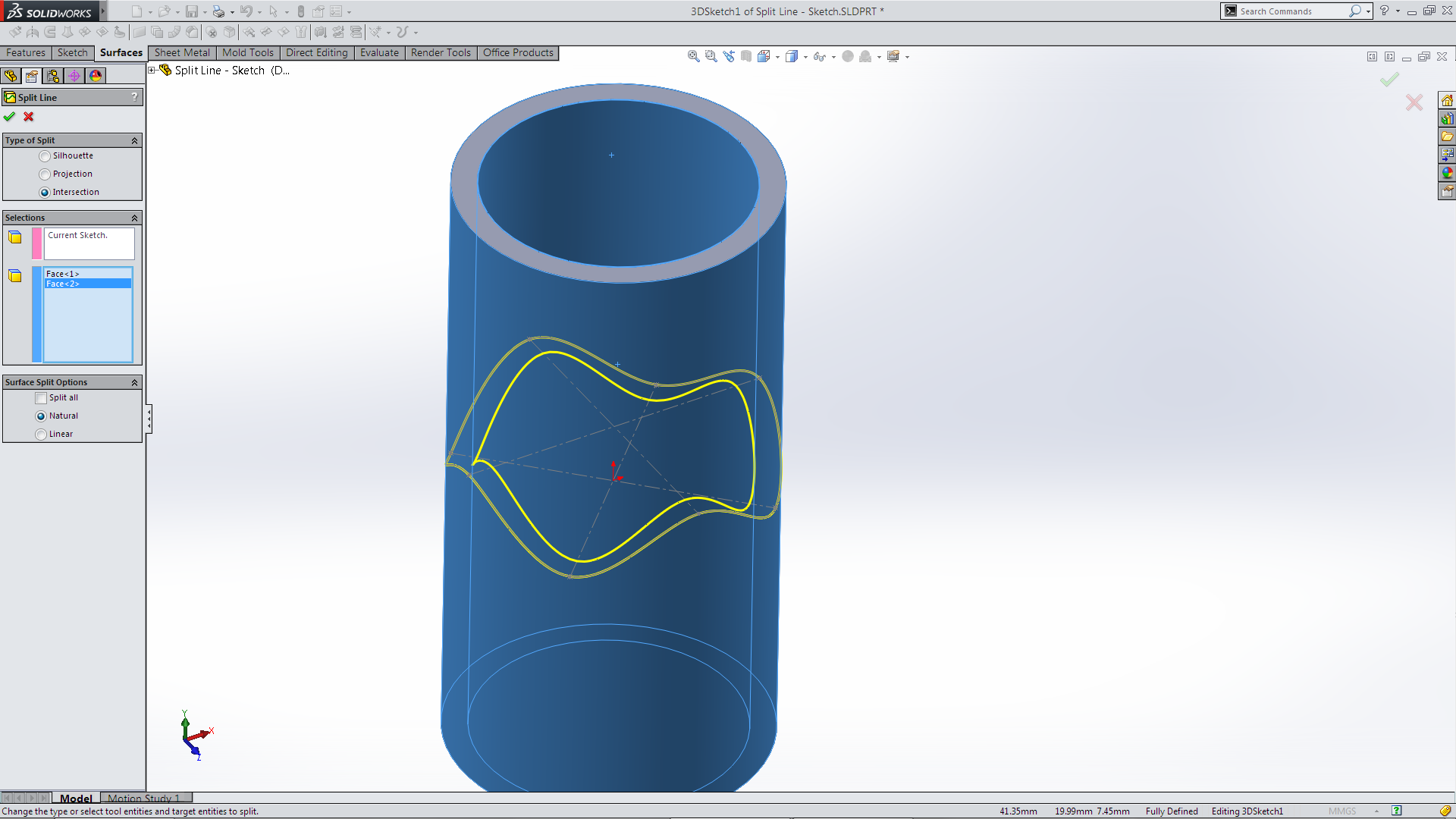 Using Delete Face (from the Surface Toolbar) Deleted the outer, inner & top face
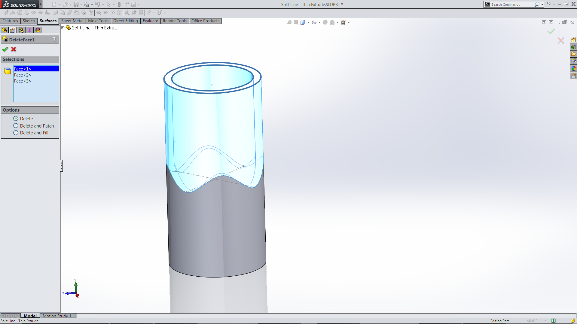 Which changes the Solid Body into a Surface Body! To “seal” back up I used the Boundary Surface (I could have used Surface Sweep)
 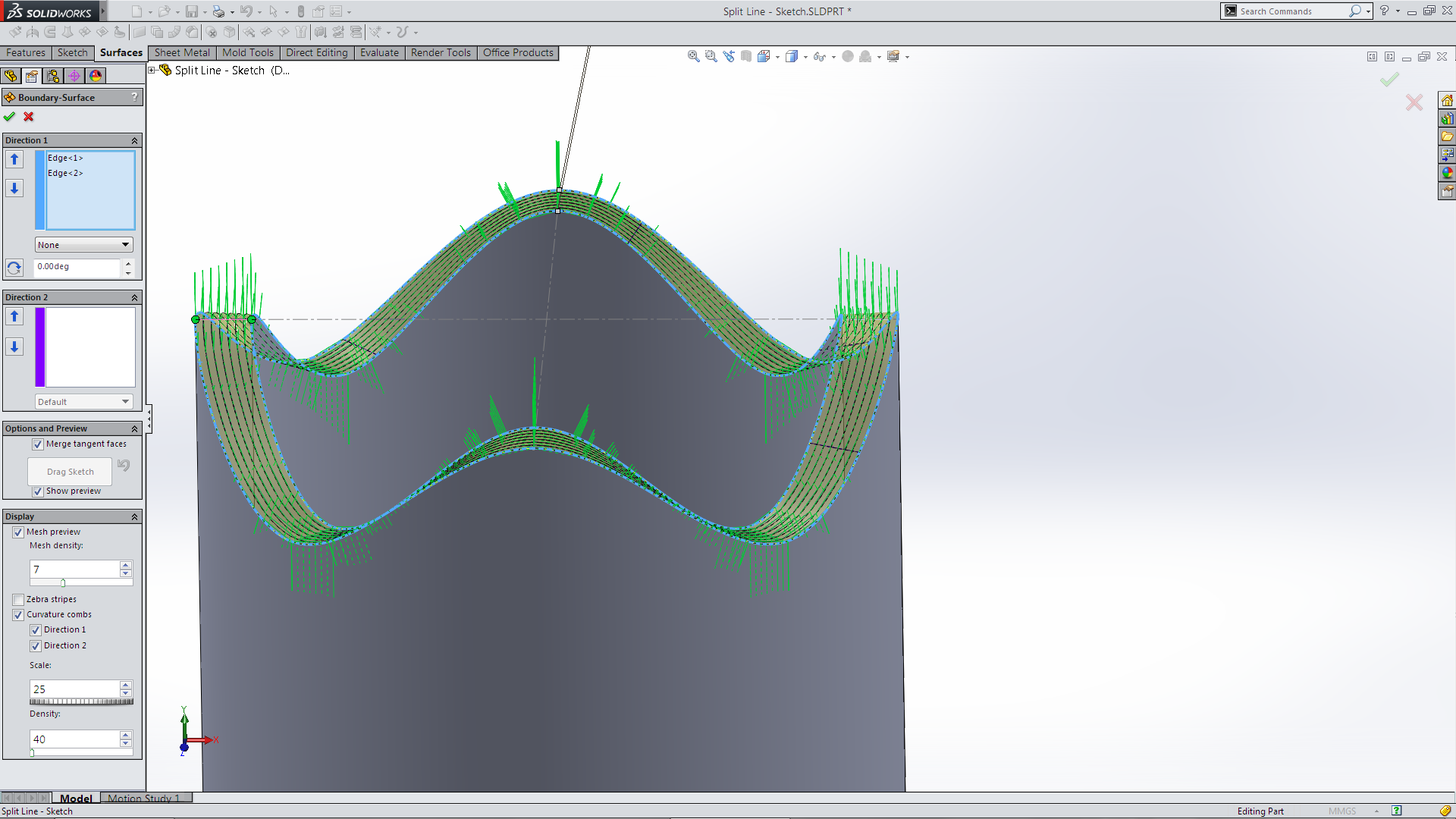 Knit the two surface bodies and select -Try to Form Solid.
 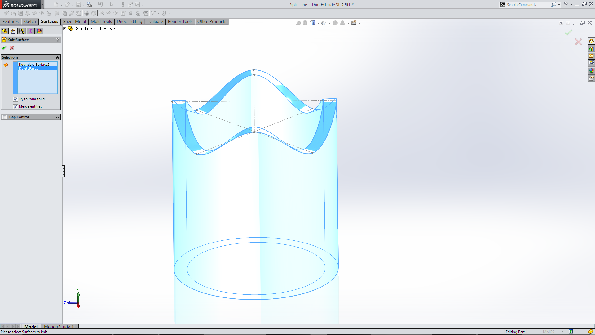 To create the solid completed Part! Which is much better!
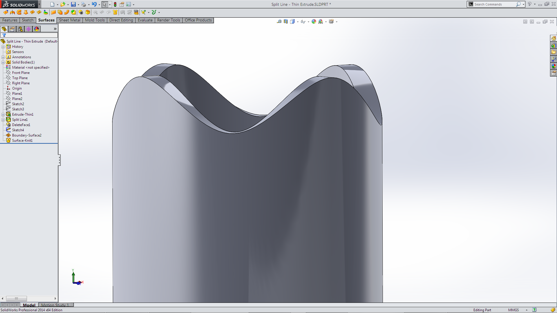 What if I didn’t start with a Thin Extrude?
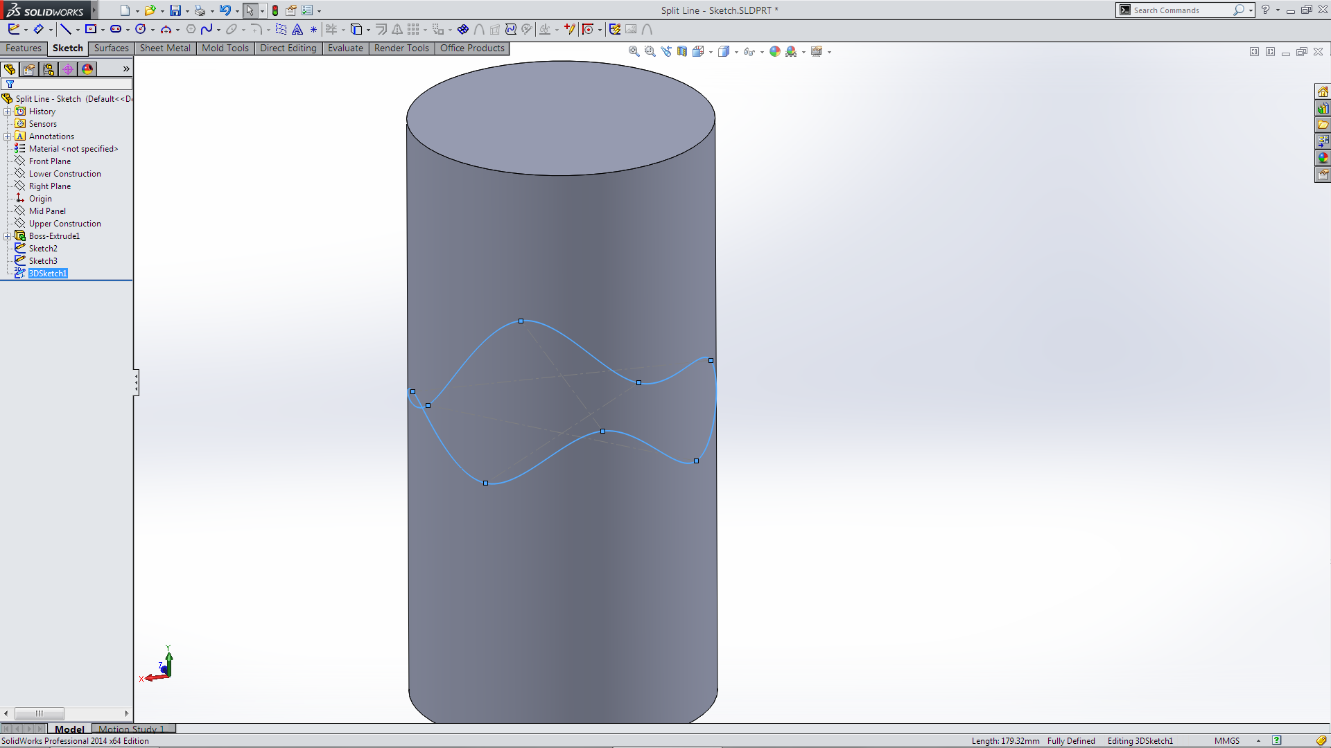 Split Line the Surface. Delete Face, outer and top faces. Not what I wanted so I added the bottom face.
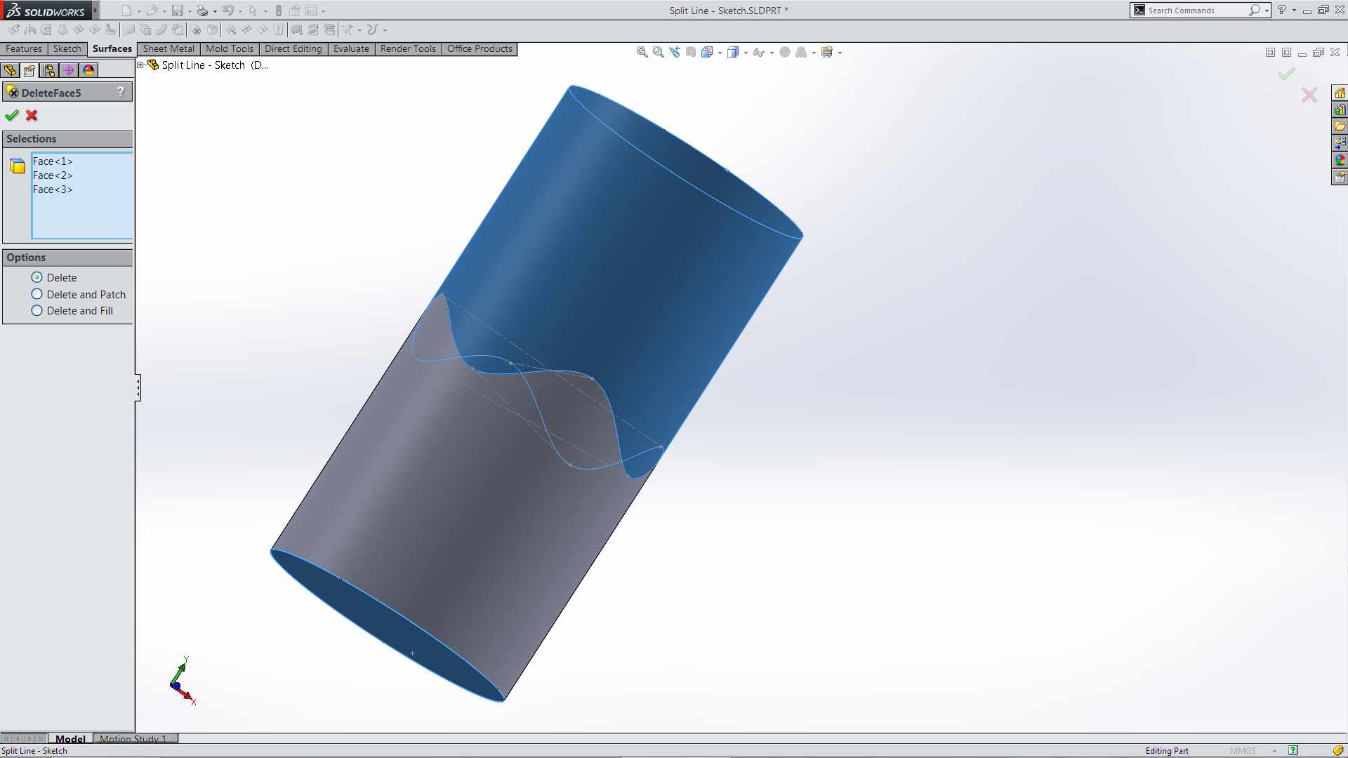 Which left the outer surface which I then could use the Thicken feature.
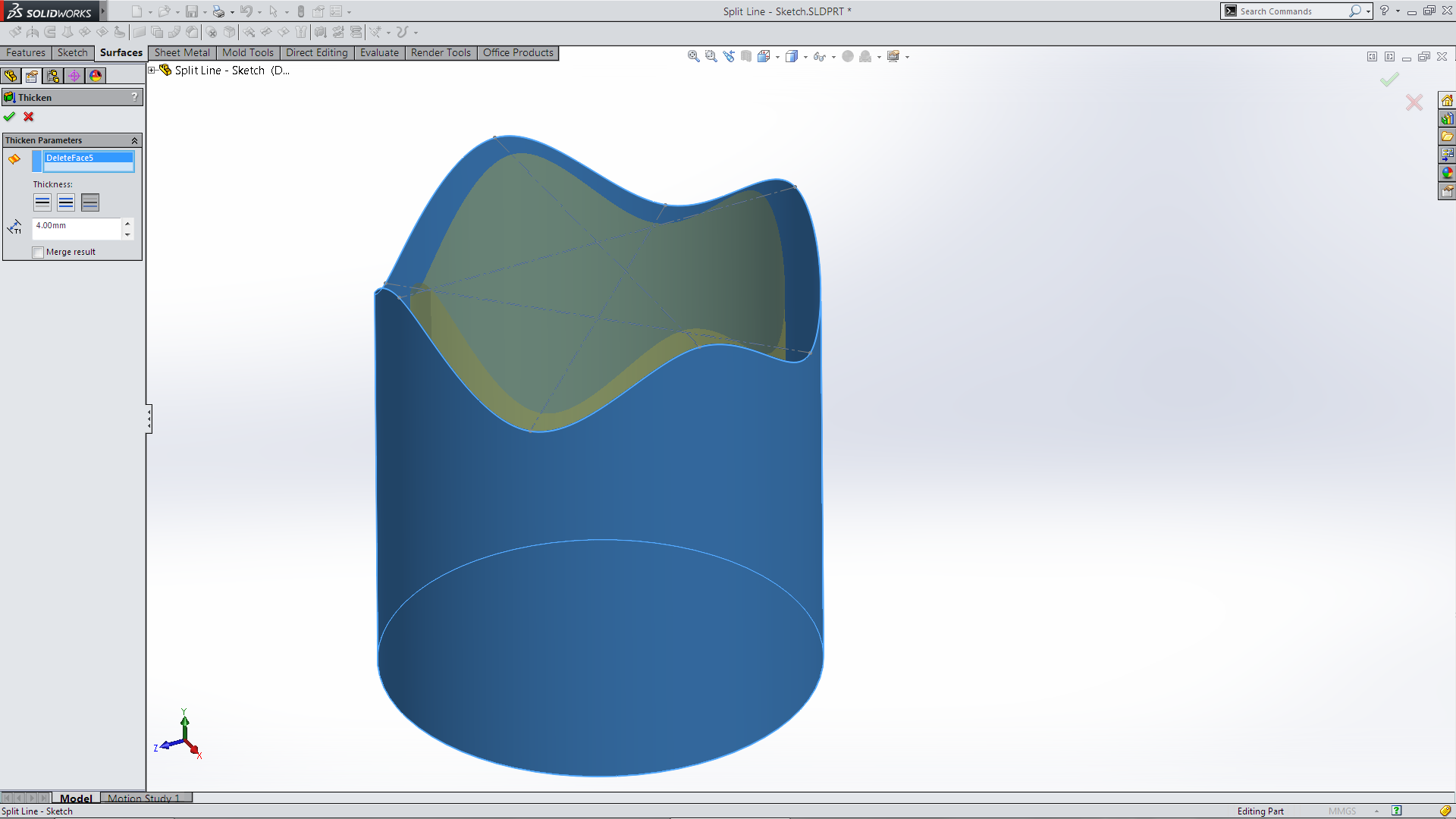 Which gave the required part. So by now I have ventured far away from my original thoughts.
 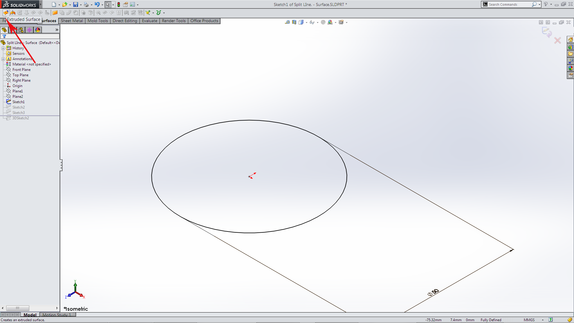 I may as well abandon using Solids all together and start by Surface Extrude the original sketch circle Create the same Spline on Surface.
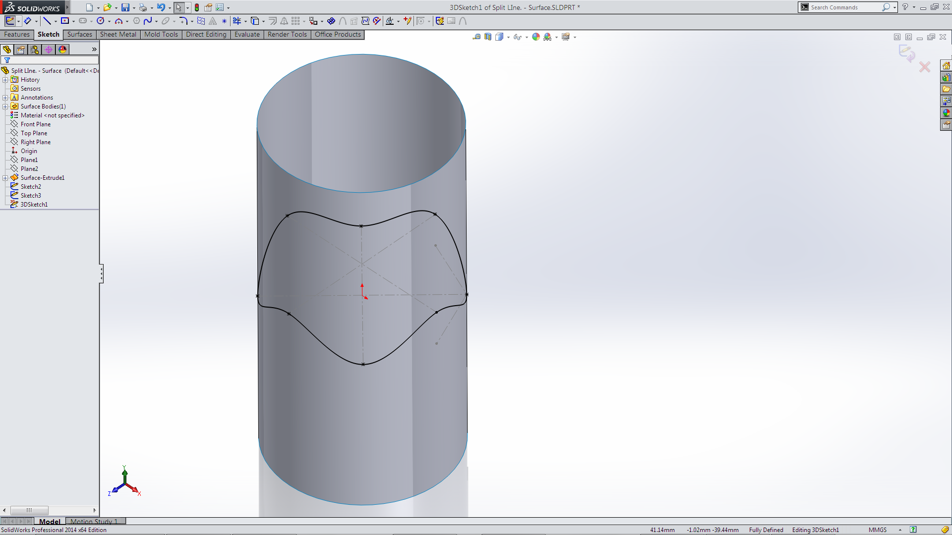 Use the Split Line and Delete Face tools (as before)
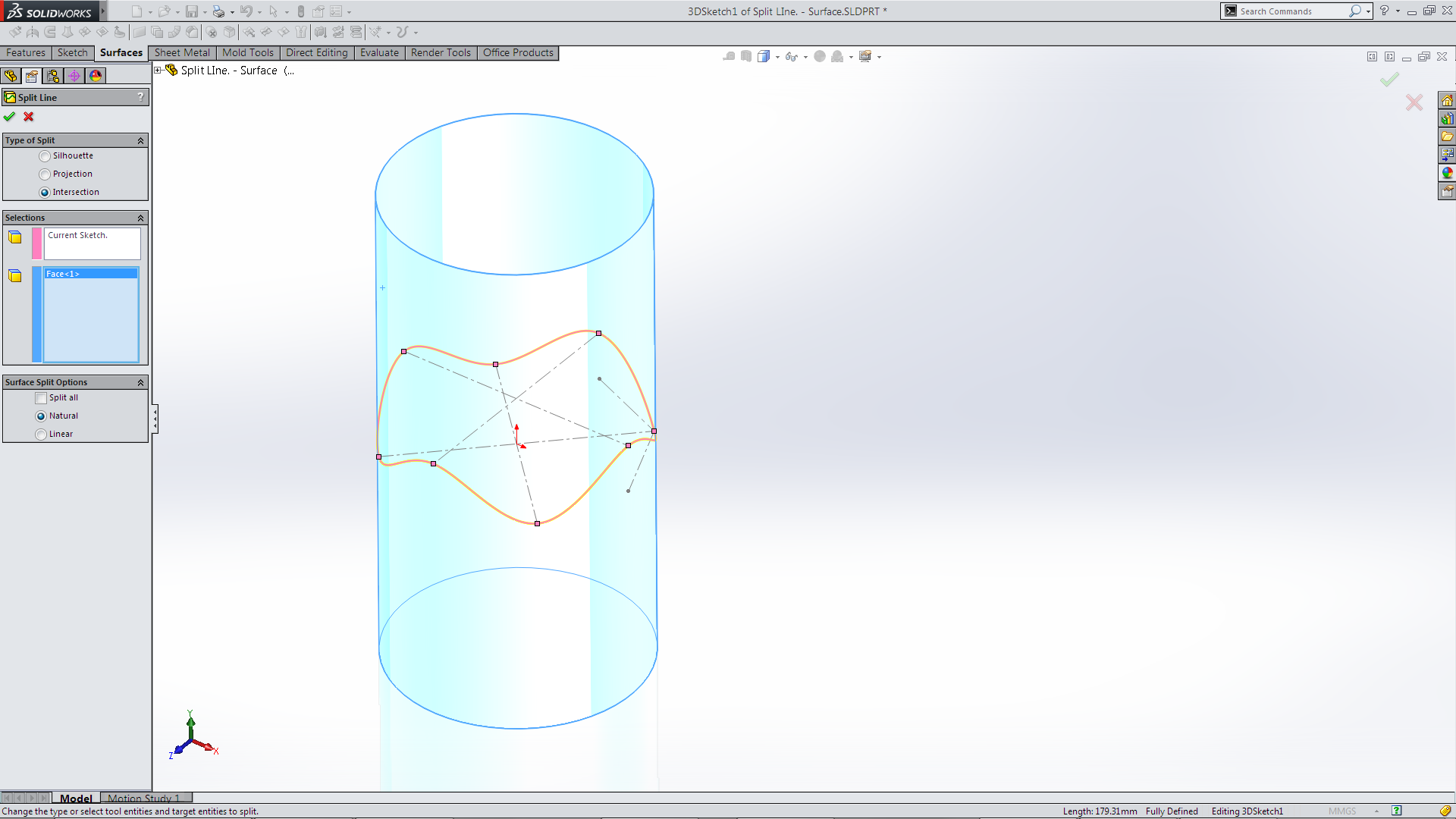 Then use the Thicken feature to create the required Part!
 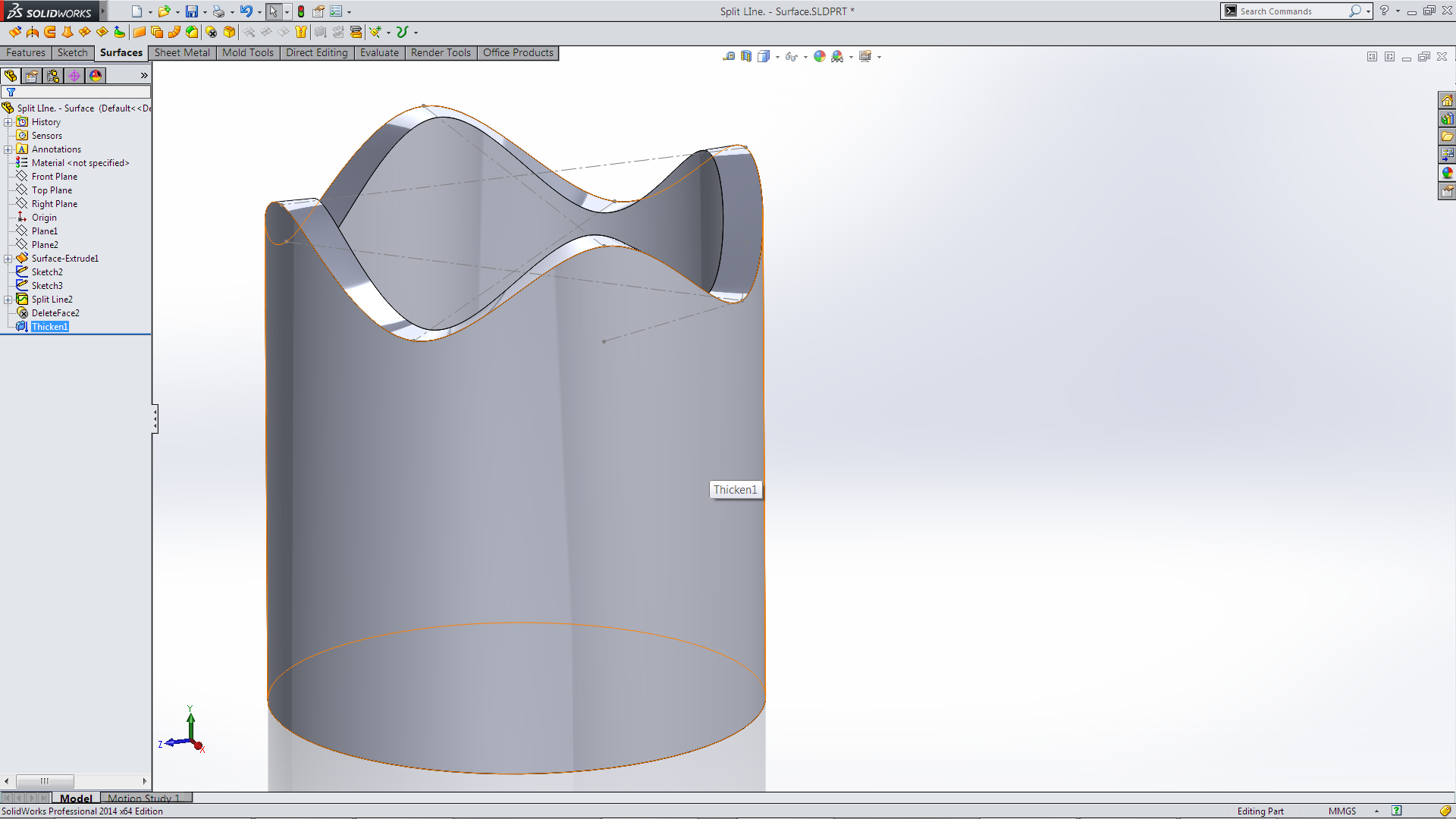 This lead me in a few different directions that I wasn’t quite expecting and finished up somewhere I didn’t quite expect! But it was an interesting exercise. It which gave me the opportunity to use a few different tools that I normally wouldn’t have and that is never a bad thing!

Leave a comment