
I had grand plans for Beta testing SolidWorks 2013 but as John Lennon once sang : “Life is what happens to you while you’re busy making other plans” (Beautiful Boy (Darling Boy) 1980). So my grand plans turned into Reading the “What’s New” and testing a few features that took my interests.
I’ve always held the opinion that the simplest of improvements are often the most productive. Which is what I believe that “Automatically Add Dimensions to Sketches” will become. Maybe not for those who have been using the product for a while (breaking habits may be hard) but certainly for new uses.
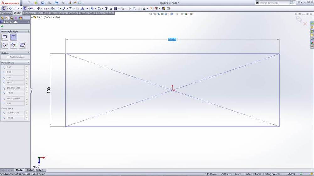
It first has to be set via Systems Options – Enable on screen numeric input on entity creation.

In the case of a rectrangular sketch, if you LMB (left mouse button), drag and continue to HOLD down the LMB you can see that the first dimension is highlighted. You can then type in the dimension value and select Enter.

The second dimension is then highlighted. You can then type in this dimension value and select Enter. For those new to SolidWorks I think that this would become the standard way of creating most sketch dimensions
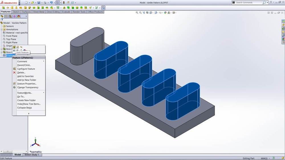
When I first saw Varying Pattern Instances at SolidWorks World 2012 I thought it was an interesting feature, so I was keen to actually try. Create (in this case) a Linear Pattern and then edit the Feature.
Select (tick) Instances to Vary, then select the shown dimensions.

You can then LMB the required Instance to vary and select Modify Instance
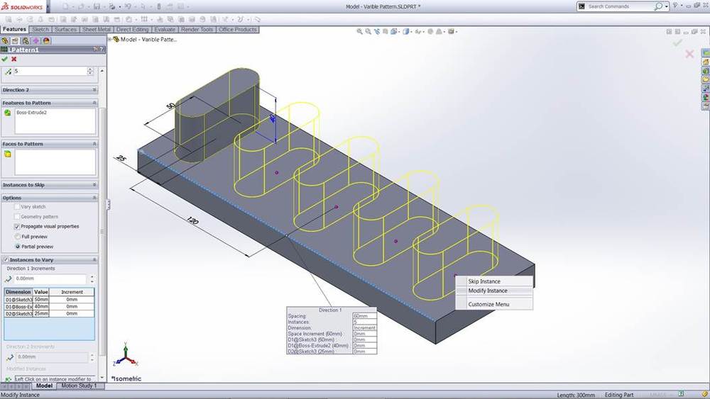
This opens the dialogue box for that Instance. Which then allows the change of any of the dimension of that instance

Pattern with the changed Instance.

I’ve always liked Drawings and the ease of how SolidWorks creates them. Although I don’t use Sectioning on a regular bases I like the look of the New Interface of the Section Tool. Now when you select Section View you only see the one section.

Now when you start to add the Cutting line you see automatic snapping
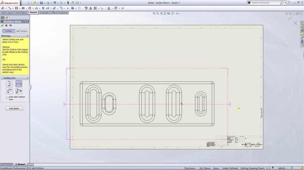
When positioned the cutting line opens a tool bar which allows either acceptance of the cutting line or options of Single, Notched or arc Offsets

By selecting one of the options you can then add the additional line(s) of the cutting line

Insert Multiple Parts was one of those tools I could have used years ago. I did a post on Task Scheduler which pointed out how I could have done with that tool years before it came out. I explained where I was converting hundreds (thousands!) of iges files to SolidWorks part files and then the need to create assemblies. Insert Multiple Parts would now compliment the use of Task Scheduler. Now when you Browse for Parts, for an Assembly, you can then select multiple Parts (Windows Shift & Highlight or Ctrl Select)
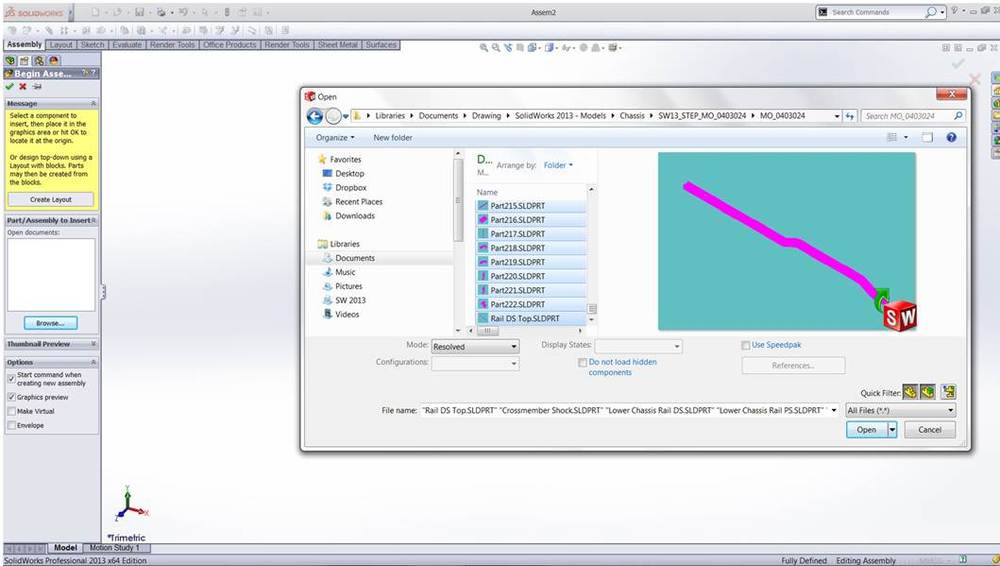
Which will bring all the selected parts into the Parts/ Assembly to Insert box.

In my case all of the parts have been created with their position from the Origin so I can simply drag all to the graphic area and Enter (select tick)

It takes a little while when you’re inserting a hundred or so parts at a time but still much quicker than having to drag in each part individually.

There are some nice additions to the Measurement Tool. You now have the option of setting Custom Distance
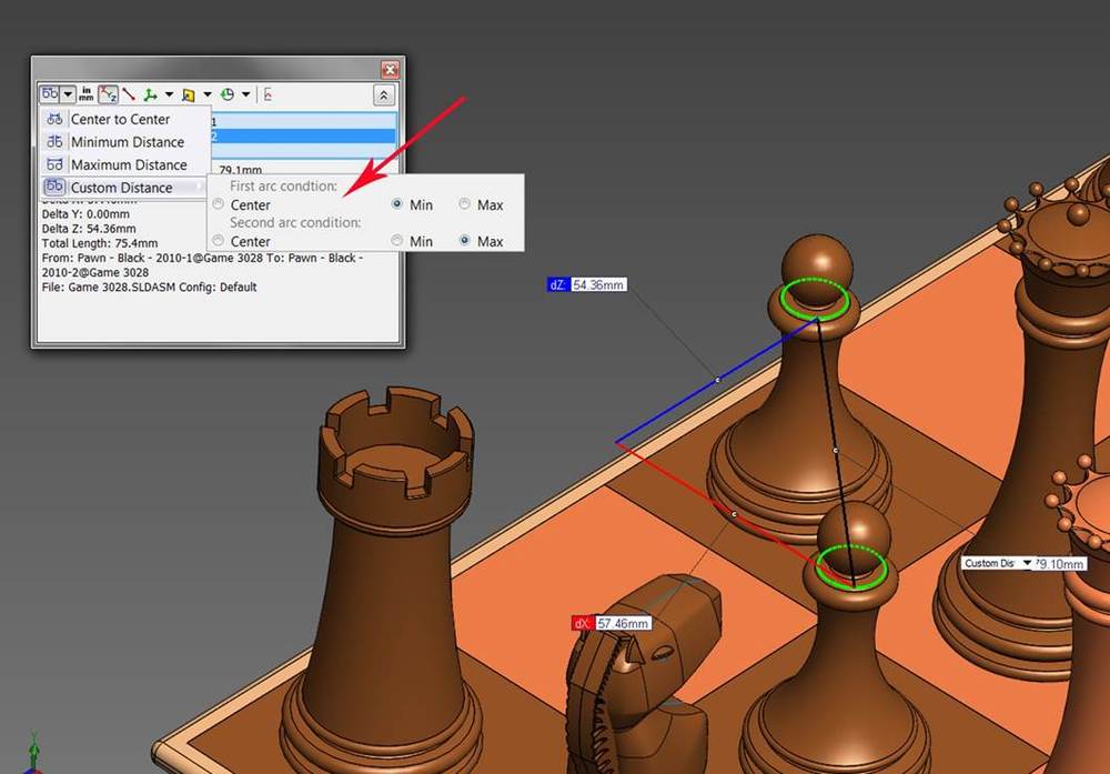
The interface now supplies additional information in Assemblies: “From (name of part) “To” (name of part) as well as File (name) and Configuration.

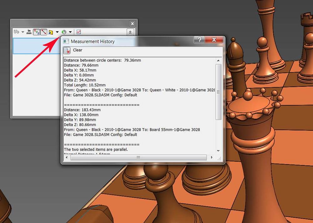
A Measurement History Interface has been added (which may come in handy for those of us with Short term memory issues!)
After my first look at SolidWorks 2013 there appears to be a little something for everyone. For me there are some very nice additions to PhotoView 360 but that’s for another post.
For now that’s just a few things that I like!

Leave a comment